SiFire-Easy-40/250-226-18,5/17,7EDJ
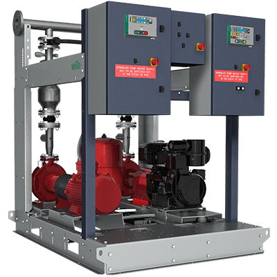
Pressure-boosting systems for firefighting according to EN 12845. Consists of 1 or 2 pumps, depending on the module, with horizontal baseplate - EN 733 - with spacer coupling, electric or diesel motor and a multistage, vertical electric jockey pump.
Pressure boosting system as a fully automatic compact unit for fire fighting purposes in accordance with EN 12845. Consisting of 2 pumps (main/standby) with horizontal base frame - EN 733 - with spacer coupling, one with an electric motor and one with a diesel motor and multistage vertical electric jockey pump, diaphragm pressure vessel (capacity: 20 l) and one switch cabinet per pump, fixed to a robust support structure. Model EC-Fire E for the electric motor and model EC-Fire D for the diesel motor, both equipped with Easy Controller, plus model EC-Fire J for the jockey pump, solid construction made of special profiled parts with cut-outs for forklift trucks and hooks to ensure trouble-free, safe transportation. Height-adjustable bracket for the outlet manifold, special base plate for the diesel motor which reduces the transfer of vibrations considerably and increases the reliability and service life. A circuit with dual pressure switch, pressure gauge, non-return valve, valve (secured from use by unauthorised personnel) for the main pump and standby pump for automatic start. The cables are concealed in the construction and protected against bumps and cuts. Equipped with a diaphragm installed directly on the main/standby pump housing as standard, to prevent overheating in the event of zero flow. Only for the model with diesel motor: Fuel tank with level sensor and sufficient volume for six hours of autonomous operation, as well as 2 batteries on the base frame and battery charging units on the EC-Fire switch cabinet. Independent anti-vibration base frame for the diesel motor pump. One switchgear EC-Fire E and one EC-Fire D plus EC-Fire J for fire extinguishing systems in accordance with EN 12845. Switchgears integrated in a sheet metal enclosure in accordance with protection class IP54. Optimum regulation and ease of use by EC-Fire control with direct display of the current operating status, with symbol-based multilingual LCD display, easy user interface with simple menu navigation, buttons for quick setting of parameters. Communicative controller for monitoring system operation. The system has been mounted on the base frame with wires and pipes are ready for connection. Inlet pressure: The maximum inlet pressure must be taken into account when designing the system configuration (see Technical data). The maximum permissible inlet pressure is calculated from the maximum operating pressure of the system minus the maximum pumping head of the pump at Q = 0. For sprinkler systems in accordance with EN 12845, the water pressure should not exceed 12 bar. In sprinkler systems with a pronounced slope, in which the difference in height between the highest and lowest sprinkler is more than 45 m, the water pressure can be higher than 12 bar at the pump outlet or in the piping, provided that all of the system components are designed for this pressure level. Installation of the pressure boosting pump under suction conditions. For the main/standby pump, it is necessary to install a supply tank with connection to the discharge pipe above the pump. Volume flow Up to 350 m³/h (97 l/s) system configuration for the main/standby pump. Switchgears/control devices for fire water supply systems Wilo-Control EC-Fire E (main pump with electric motor) Hardware: Fully electronic central control unit, installed in a painted steel enclosure, protection class IP54, control and display devices on the front door Features and functions: The design of the control device depends on the power of the connected pump (start via DOL or star-delta connection). The device comprises the following components: *Main switch: For switching the switchgear on and off. (For unauthorised use in the event of a fire) *Display: Display built into the door of the switch cabinet for operation and display purposes. Shows the operating data and the operating status of the pump and the controller using symbols. Menus are selected and parameters entered using the buttons on the front door *Microprocessor: Microprocessor PLC realised by programming, power supply unit and I/O wiring. The configuration of the programming depends on the system and the sprinkler system *Indicators: Long-life signal lamps indicate the operational readiness, motor operation and operation of the pump, the activation of the pressure switch and float switch, a false start, manual start and manual stop *Buttons: Buttons for manual start and manual stop, the lamp test and menu selection *Fuse protection: Fuses which tolerate the starting current for at least 20 s *Motor startup: Contactor for direct-on-line starting, up to 22 kW, for higher power levels start via star-delta connection *Motor protection: Only for signalling *Monitoring of the water supply: By means of a float switch to ensure a minimum water level of 2/3 of the supply tank is always maintained *Performance monitoring: Power supply and performance of the pump *Combined signal report: All types of error are displayed via a common error indicator *Individual signal report: The important false start error message is displayed via an individual error indicator *Error message and acknowledgement: All error messages are displayed via LEDs, shown in the display as an error code and must be acknowledged Software: *Factory-programmed for fully automatic operation *Information regarding voltage, electric current and power of the pump *Menu navigation with clear text display Conforms to the following standards: *Fixed Firefighting Systems - Automatic Sprinkler Systems - (EN 12845), part for pumps with electric motor *Electrical Equipment of Machines (EN 60204-1) *Low-voltage Switchgear and Controlgear Assemblies (EN 61439-1 and EN 61439-2) *EMC - Electromagnetic Compatibility for Industrial Environments (EN 61000-6-2) *EMC - Emission Standard for Residential, Commercial and Light-Industrial Environments (EN 61000-6-3) Function description: Wilo EC-Fire E control devices can be used to control pumps with an electric motor, sensors for pump management and the level of information. The microprocessor-controlled switchgear is used to control and regulate all required functions of a pressure boosting system according to EN 12845, for test purposes or actual sprinkler events. The operating logic for the fire extinguishing unit is based on the cascade calibration of the pressure switches for starting the pump. If a large amount of water is requested due to the opening of one or more circuits or due to a defective sprinkler, the pressure in the system decreases. As a result, the main pump is started using switchgear. If the electric main pump does not start in systems with multiple pumps (for example due to problems with the power supply), the pressure drop will activate the pressure switch of the standby pump, which starts this pump. In some cases, two or more electric pumps can be used. As soon as the sprinkler circuit or gate valve, via which the sprinkler heads are supplied, is closed, pressure is built up in the system. The stop buttons on the front door must then be pressed to stop the pump. Wilo-Control EC-Fire D (main pump with diesel motor) Hardware: Fully electronic central control unit, installed in a painted steel enclosure, protection class IP54, control and display devices on the front door Features and functions: The design of the control device depends on the power of the connected pump. The device comprises the following components: *Main switch: For switching the switchgear on and off. (For unauthorised use in the event of a fire) *Display: Display built into the door of the switch cabinet for operation and display purposes. Shows the operating data and the operating status of the pump and the controller using symbols. Menus are selected and parameters entered using the buttons on the front door *Microprocessor: Microprocessor PLC realised by programming, power supply unit and I/O wiring. The configuration of the programming depends on the system and the sprinkler system *Indicators: Longlife signal lamps which indicate the following: Operation of the pump, activation of the pressure switch, activation of the float switch, deactivation of automatic mode, deactivation of the motor heater, temperature alarm, oil pressure alarm, false start, belt alarm, low fuel level, running battery charger, low battery status, battery charger alarm, manual stop *Buttons: Push button for manual stop, manual start battery A, manual start battery B, lamp test and acknowledgement of alarms and warning messages, as well as menu selection *Fuse protection: Fuses for heating and battery charging unit in the switchgear *Motor startup: Automatically via 2 alternating batteries or directly with the start button on the front panel *Motor protection: Monitoring of typical operating parameters of the diesel motor (temperature, oil pressure, etc.) without stopping *Performance monitoring: Speed monitoring of the diesel engine *Battery monitoring: Monitoring of charging voltage, charging current and charging errors *Monitoring of the water supply: By means of a float switch to ensure a minimum water level of 2/3 of the supply tank is always maintained *Monitoring of the power supply: Error message from the battery charging unit in the event of a failure of the power supply *Combined signal report: All types of error are displayed via a common error indicator *Individual signal report: Important individual errors are indicated via individual error indicators *Error message and acknowledgement: All error messages are indicated by LEDs, and must be acknowledged Software: *Factory-programmed for fully automatic operation *Information regarding motor speed, charging voltage and charging current. *Menu navigation with clear text display Conforms to the following standards: *Fixed Firefighting Systems - Automatic Sprinkler Systems - (EN 12845), part for pumps with diesel motor *Electrical Equipment of Machines (EN 60204-1) *Low-voltage Switchgear and Controlgear Assemblies (EN 61439-1 and EN 61439-2) *EMC - Electromagnetic Compatibility for Industrial Environments (EN 61000-6-2) *EMC - Emission Standard for Residential, Commercial and Light-Industrial Environments (EN 61000-6-3) Function description: Wilo EC-Fire D control devices can be used to control pumps with a diesel motor, sensors for pump management and the level of information. The microprocessor-controlled switchgear is used to control and regulate all required functions of a pressure boosting system according to EN 12845, for test purposes or actual sprinkler events. The operating logic for the fire extinguishing unit is based on the cascade calibration of the pressure switches for starting the pump. The pressure in the system decreases if a large quantity of water is requested due to the opening of one or more circuits or due to a defective sprinkler. As a result, the main pump is started using switchgear. As soon as the sprinkler circuit or gate valve, via which the sprinkler heads are supplied, is closed, pressure is built up in the system. The stop buttons on the front door must then be pressed to stop the pump. Wilo-Control EC-Fire J (jockey pump with electric motor) Hardware: Fully electromechanical control unit, installed in a painted steel enclosure, protection class IP54, control devices and buttons on the front door Features and functions: The design of the control device depends on the power of the connected pump. The device comprises the following components: *Main switch: For switching the switchgear on and off *Indicators: Longlife signal lamps, which indicate the operational readiness of the pump, operation of the pump and collective errors *Switches: Rotary switch for setting the manual mode or automatic mode *Motor startup: Direct contactor *Motor protection: Switch for protection against short-circuits and overloads *Individual signal report: Motor error message (short-circuit, overload) *Error message and acknowledgement: The motor error message is indicated via corresponding LEDs. The error is acknowledged when the motor protection switch is restarted Conforms to the following standards: *Fixed Firefighting Systems - Automatic Sprinkler Systems - (EN 12845), part for jockey pumps *Electrical Equipment of Machines (EN 60204-1) *Low-voltage Switchgear and Controlgear Assemblies (EN 61439-1 and EN 61439-2) *EMC - Electromagnetic Compatibility for Industrial Environments (EN 61000-6-2) *EMC - Emission Standard for Residential, Commercial and Light-Industrial Environments (EN 61000-6-3) Function description: Wilo-Control EC-Fire J units can be used to control jockey pumps with an electric motor and sensors according to EN 12845, as well as for test purposes and operation of the sprinkler system. The operating logic for the fire extinguishing unit is based on the cascade calibration of the pressure switches for starting the pump. The jockey pump, which is used for pressure boosting, is started first and ensures that the system is filled with water and that it remains pressurised. It is activated in the event of a pressure drop in the system. A properly calibrated pressure switch is used for controlled starting and stopping procedures.
SiFire-Easy-40/250-244-22/26,5EDJ
Pressure-boosting systems for firefighting according to EN 12845. Consists of 1 or 2 pumps, depending on the module, with horizontal baseplate - EN 733 - with spacer coupling, electric or diesel motor and a multistage, vertical electric jockey pump.
Pressure boosting system as a fully automatic compact unit for fire fighting purposes in accordance with EN 12845. Consisting of 2 pumps (main/standby) with horizontal base frame - EN 733 - with spacer coupling, one with an electric motor and one with a diesel motor and multistage vertical electric jockey pump, diaphragm pressure vessel (capacity: 20 l) and one switch cabinet per pump, fixed to a robust support structure. Model EC-Fire E for the electric motor and model EC-Fire D for the diesel motor, both equipped with Easy Controller, plus model EC-Fire J for the jockey pump, solid construction made of special profiled parts with cut-outs for forklift trucks and hooks to ensure trouble-free, safe transportation. Height-adjustable bracket for the outlet manifold, special base plate for the diesel motor which reduces the transfer of vibrations considerably and increases the reliability and service life. A circuit with dual pressure switch, pressure gauge, non-return valve, valve (secured from use by unauthorised personnel) for the main pump and standby pump for automatic start. The cables are concealed in the construction and protected against bumps and cuts. Equipped with a diaphragm installed directly on the main/standby pump housing as standard, to prevent overheating in the event of zero flow. Only for the model with diesel motor: Fuel tank with level sensor and sufficient volume for six hours of autonomous operation, as well as 2 batteries on the base frame and battery charging units on the EC-Fire switch cabinet. Independent anti-vibration base frame for the diesel motor pump. One switchgear EC-Fire E and one EC-Fire D plus EC-Fire J for fire extinguishing systems in accordance with EN 12845. Switchgears integrated in a sheet metal enclosure in accordance with protection class IP54. Optimum regulation and ease of use by EC-Fire control with direct display of the current operating status, with symbol-based multilingual LCD display, easy user interface with simple menu navigation, buttons for quick setting of parameters. Communicative controller for monitoring system operation. The system has been mounted on the base frame with wires and pipes are ready for connection. Inlet pressure: The maximum inlet pressure must be taken into account when designing the system configuration (see Technical data). The maximum permissible inlet pressure is calculated from the maximum operating pressure of the system minus the maximum pumping head of the pump at Q = 0. For sprinkler systems in accordance with EN 12845, the water pressure should not exceed 12 bar. In sprinkler systems with a pronounced slope, in which the difference in height between the highest and lowest sprinkler is more than 45 m, the water pressure can be higher than 12 bar at the pump outlet or in the piping, provided that all of the system components are designed for this pressure level. Installation of the pressure boosting pump under suction conditions. For the main/standby pump, it is necessary to install a supply tank with connection to the discharge pipe above the pump. Volume flow Up to 350 m³/h (97 l/s) system configuration for the main/standby pump. Switchgears/control devices for fire water supply systems Wilo-Control EC-Fire E (main pump with electric motor) Hardware: Fully electronic central control unit, installed in a painted steel enclosure, protection class IP54, control and display devices on the front door Features and functions: The design of the control device depends on the power of the connected pump (start via DOL or star-delta connection). The device comprises the following components: *Main switch: For switching the switchgear on and off. (For unauthorised use in the event of a fire) *Display: Display built into the door of the switch cabinet for operation and display purposes. Shows the operating data and the operating status of the pump and the controller using symbols. Menus are selected and parameters entered using the buttons on the front door *Microprocessor: Microprocessor PLC realised by programming, power supply unit and I/O wiring. The configuration of the programming depends on the system and the sprinkler system *Indicators: Long-life signal lamps indicate the operational readiness, motor operation and operation of the pump, the activation of the pressure switch and float switch, a false start, manual start and manual stop *Buttons: Buttons for manual start and manual stop, the lamp test and menu selection *Fuse protection: Fuses which tolerate the starting current for at least 20 s *Motor startup: Contactor for direct-on-line starting, up to 22 kW, for higher power levels start via star-delta connection *Motor protection: Only for signalling *Monitoring of the water supply: By means of a float switch to ensure a minimum water level of 2/3 of the supply tank is always maintained *Performance monitoring: Power supply and performance of the pump *Combined signal report: All types of error are displayed via a common error indicator *Individual signal report: The important false start error message is displayed via an individual error indicator *Error message and acknowledgement: All error messages are displayed via LEDs, shown in the display as an error code and must be acknowledged Software: *Factory-programmed for fully automatic operation *Information regarding voltage, electric current and power of the pump *Menu navigation with clear text display Conforms to the following standards: *Fixed Firefighting Systems - Automatic Sprinkler Systems - (EN 12845), part for pumps with electric motor *Electrical Equipment of Machines (EN 60204-1) *Low-voltage Switchgear and Controlgear Assemblies (EN 61439-1 and EN 61439-2) *EMC - Electromagnetic Compatibility for Industrial Environments (EN 61000-6-2) *EMC - Emission Standard for Residential, Commercial and Light-Industrial Environments (EN 61000-6-3) Function description: Wilo EC-Fire E control devices can be used to control pumps with an electric motor, sensors for pump management and the level of information. The microprocessor-controlled switchgear is used to control and regulate all required functions of a pressure boosting system according to EN 12845, for test purposes or actual sprinkler events. The operating logic for the fire extinguishing unit is based on the cascade calibration of the pressure switches for starting the pump. If a large amount of water is requested due to the opening of one or more circuits or due to a defective sprinkler, the pressure in the system decreases. As a result, the main pump is started using switchgear. If the electric main pump does not start in systems with multiple pumps (for example due to problems with the power supply), the pressure drop will activate the pressure switch of the standby pump, which starts this pump. In some cases, two or more electric pumps can be used. As soon as the sprinkler circuit or gate valve, via which the sprinkler heads are supplied, is closed, pressure is built up in the system. The stop buttons on the front door must then be pressed to stop the pump. Wilo-Control EC-Fire D (main pump with diesel motor) Hardware: Fully electronic central control unit, installed in a painted steel enclosure, protection class IP54, control and display devices on the front door Features and functions: The design of the control device depends on the power of the connected pump. The device comprises the following components: *Main switch: For switching the switchgear on and off. (For unauthorised use in the event of a fire) *Display: Display built into the door of the switch cabinet for operation and display purposes. Shows the operating data and the operating status of the pump and the controller using symbols. Menus are selected and parameters entered using the buttons on the front door *Microprocessor: Microprocessor PLC realised by programming, power supply unit and I/O wiring. The configuration of the programming depends on the system and the sprinkler system *Indicators: Longlife signal lamps which indicate the following: Operation of the pump, activation of the pressure switch, activation of the float switch, deactivation of automatic mode, deactivation of the motor heater, temperature alarm, oil pressure alarm, false start, belt alarm, low fuel level, running battery charger, low battery status, battery charger alarm, manual stop *Buttons: Push button for manual stop, manual start battery A, manual start battery B, lamp test and acknowledgement of alarms and warning messages, as well as menu selection *Fuse protection: Fuses for heating and battery charging unit in the switchgear *Motor startup: Automatically via 2 alternating batteries or directly with the start button on the front panel *Motor protection: Monitoring of typical operating parameters of the diesel motor (temperature, oil pressure, etc.) without stopping *Performance monitoring: Speed monitoring of the diesel engine *Battery monitoring: Monitoring of charging voltage, charging current and charging errors *Monitoring of the water supply: By means of a float switch to ensure a minimum water level of 2/3 of the supply tank is always maintained *Monitoring of the power supply: Error message from the battery charging unit in the event of a failure of the power supply *Combined signal report: All types of error are displayed via a common error indicator *Individual signal report: Important individual errors are indicated via individual error indicators *Error message and acknowledgement: All error messages are indicated by LEDs, and must be acknowledged Software: *Factory-programmed for fully automatic operation *Information regarding motor speed, charging voltage and charging current. *Menu navigation with clear text display Conforms to the following standards: *Fixed Firefighting Systems - Automatic Sprinkler Systems - (EN 12845), part for pumps with diesel motor *Electrical Equipment of Machines (EN 60204-1) *Low-voltage Switchgear and Controlgear Assemblies (EN 61439-1 and EN 61439-2) *EMC - Electromagnetic Compatibility for Industrial Environments (EN 61000-6-2) *EMC - Emission Standard for Residential, Commercial and Light-Industrial Environments (EN 61000-6-3) Function description: Wilo EC-Fire D control devices can be used to control pumps with a diesel motor, sensors for pump management and the level of information. The microprocessor-controlled switchgear is used to control and regulate all required functions of a pressure boosting system according to EN 12845, for test purposes or actual sprinkler events. The operating logic for the fire extinguishing unit is based on the cascade calibration of the pressure switches for starting the pump. The pressure in the system decreases if a large quantity of water is requested due to the opening of one or more circuits or due to a defective sprinkler. As a result, the main pump is started using switchgear. As soon as the sprinkler circuit or gate valve, via which the sprinkler heads are supplied, is closed, pressure is built up in the system. The stop buttons on the front door must then be pressed to stop the pump. Wilo-Control EC-Fire J (jockey pump with electric motor) Hardware: Fully electromechanical control unit, installed in a painted steel enclosure, protection class IP54, control devices and buttons on the front door Features and functions: The design of the control device depends on the power of the connected pump. The device comprises the following components: *Main switch: For switching the switchgear on and off *Indicators: Longlife signal lamps, which indicate the operational readiness of the pump, operation of the pump and collective errors *Switches: Rotary switch for setting the manual mode or automatic mode *Motor startup: Direct contactor *Motor protection: Switch for protection against short-circuits and overloads *Individual signal report: Motor error message (short-circuit, overload) *Error message and acknowledgement: The motor error message is indicated via corresponding LEDs. The error is acknowledged when the motor protection switch is restarted Conforms to the following standards: *Fixed Firefighting Systems - Automatic Sprinkler Systems - (EN 12845), part for jockey pumps *Electrical Equipment of Machines (EN 60204-1) *Low-voltage Switchgear and Controlgear Assemblies (EN 61439-1 and EN 61439-2) *EMC - Electromagnetic Compatibility for Industrial Environments (EN 61000-6-2) *EMC - Emission Standard for Residential, Commercial and Light-Industrial Environments (EN 61000-6-3) Function description: Wilo-Control EC-Fire J units can be used to control jockey pumps with an electric motor and sensors according to EN 12845, as well as for test purposes and operation of the sprinkler system. The operating logic for the fire extinguishing unit is based on the cascade calibration of the pressure switches for starting the pump. The jockey pump, which is used for pressure boosting, is started first and ensures that the system is filled with water and that it remains pressurised. It is activated in the event of a pressure drop in the system. A properly calibrated pressure switch is used for controlled starting and stopping procedures.
SiFire-Easy-40/250-250-30/26,5EDJ
Pressure-boosting systems for firefighting according to EN 12845. Consists of 1 or 2 pumps, depending on the module, with horizontal baseplate - EN 733 - with spacer coupling, electric or diesel motor and a multistage, vertical electric jockey pump.
Pressure boosting system as a fully automatic compact unit for fire fighting purposes in accordance with EN 12845. Consisting of 2 pumps (main/standby) with horizontal base frame - EN 733 - with spacer coupling, one with an electric motor and one with a diesel motor and multistage vertical electric jockey pump, diaphragm pressure vessel (capacity: 20 l) and one switch cabinet per pump, fixed to a robust support structure. Model EC-Fire E for the electric motor and model EC-Fire D for the diesel motor, both equipped with Easy Controller, plus model EC-Fire J for the jockey pump, solid construction made of special profiled parts with cut-outs for forklift trucks and hooks to ensure trouble-free, safe transportation. Height-adjustable bracket for the outlet manifold, special base plate for the diesel motor which reduces the transfer of vibrations considerably and increases the reliability and service life. A circuit with dual pressure switch, pressure gauge, non-return valve, valve (secured from use by unauthorised personnel) for the main pump and standby pump for automatic start. The cables are concealed in the construction and protected against bumps and cuts. Equipped with a diaphragm installed directly on the main/standby pump housing as standard, to prevent overheating in the event of zero flow. Only for the model with diesel motor: Fuel tank with level sensor and sufficient volume for six hours of autonomous operation, as well as 2 batteries on the base frame and battery charging units on the EC-Fire switch cabinet. Independent anti-vibration base frame for the diesel motor pump. One switchgear EC-Fire E and one EC-Fire D plus EC-Fire J for fire extinguishing systems in accordance with EN 12845. Switchgears integrated in a sheet metal enclosure in accordance with protection class IP54. Optimum regulation and ease of use by EC-Fire control with direct display of the current operating status, with symbol-based multilingual LCD display, easy user interface with simple menu navigation, buttons for quick setting of parameters. Communicative controller for monitoring system operation. The system has been mounted on the base frame with wires and pipes are ready for connection. Inlet pressure: The maximum inlet pressure must be taken into account when designing the system configuration (see Technical data). The maximum permissible inlet pressure is calculated from the maximum operating pressure of the system minus the maximum pumping head of the pump at Q = 0. For sprinkler systems in accordance with EN 12845, the water pressure should not exceed 12 bar. In sprinkler systems with a pronounced slope, in which the difference in height between the highest and lowest sprinkler is more than 45 m, the water pressure can be higher than 12 bar at the pump outlet or in the piping, provided that all of the system components are designed for this pressure level. Installation of the pressure boosting pump under suction conditions. For the main/standby pump, it is necessary to install a supply tank with connection to the discharge pipe above the pump. Volume flow Up to 350 m³/h (97 l/s) system configuration for the main/standby pump. Switchgears/control devices for fire water supply systems Wilo-Control EC-Fire E (main pump with electric motor) Hardware: Fully electronic central control unit, installed in a painted steel enclosure, protection class IP54, control and display devices on the front door Features and functions: The design of the control device depends on the power of the connected pump (start via DOL or star-delta connection). The device comprises the following components: *Main switch: For switching the switchgear on and off. (For unauthorised use in the event of a fire) *Display: Display built into the door of the switch cabinet for operation and display purposes. Shows the operating data and the operating status of the pump and the controller using symbols. Menus are selected and parameters entered using the buttons on the front door *Microprocessor: Microprocessor PLC realised by programming, power supply unit and I/O wiring. The configuration of the programming depends on the system and the sprinkler system *Indicators: Long-life signal lamps indicate the operational readiness, motor operation and operation of the pump, the activation of the pressure switch and float switch, a false start, manual start and manual stop *Buttons: Buttons for manual start and manual stop, the lamp test and menu selection *Fuse protection: Fuses which tolerate the starting current for at least 20 s *Motor startup: Contactor for direct-on-line starting, up to 22 kW, for higher power levels start via star-delta connection *Motor protection: Only for signalling *Monitoring of the water supply: By means of a float switch to ensure a minimum water level of 2/3 of the supply tank is always maintained *Performance monitoring: Power supply and performance of the pump *Combined signal report: All types of error are displayed via a common error indicator *Individual signal report: The important false start error message is displayed via an individual error indicator *Error message and acknowledgement: All error messages are displayed via LEDs, shown in the display as an error code and must be acknowledged Software: *Factory-programmed for fully automatic operation *Information regarding voltage, electric current and power of the pump *Menu navigation with clear text display Conforms to the following standards: *Fixed Firefighting Systems - Automatic Sprinkler Systems - (EN 12845), part for pumps with electric motor *Electrical Equipment of Machines (EN 60204-1) *Low-voltage Switchgear and Controlgear Assemblies (EN 61439-1 and EN 61439-2) *EMC - Electromagnetic Compatibility for Industrial Environments (EN 61000-6-2) *EMC - Emission Standard for Residential, Commercial and Light-Industrial Environments (EN 61000-6-3) Function description: Wilo EC-Fire E control devices can be used to control pumps with an electric motor, sensors for pump management and the level of information. The microprocessor-controlled switchgear is used to control and regulate all required functions of a pressure boosting system according to EN 12845, for test purposes or actual sprinkler events. The operating logic for the fire extinguishing unit is based on the cascade calibration of the pressure switches for starting the pump. If a large amount of water is requested due to the opening of one or more circuits or due to a defective sprinkler, the pressure in the system decreases. As a result, the main pump is started using switchgear. If the electric main pump does not start in systems with multiple pumps (for example due to problems with the power supply), the pressure drop will activate the pressure switch of the standby pump, which starts this pump. In some cases, two or more electric pumps can be used. As soon as the sprinkler circuit or gate valve, via which the sprinkler heads are supplied, is closed, pressure is built up in the system. The stop buttons on the front door must then be pressed to stop the pump. Wilo-Control EC-Fire D (main pump with diesel motor) Hardware: Fully electronic central control unit, installed in a painted steel enclosure, protection class IP54, control and display devices on the front door Features and functions: The design of the control device depends on the power of the connected pump. The device comprises the following components: *Main switch: For switching the switchgear on and off. (For unauthorised use in the event of a fire) *Display: Display built into the door of the switch cabinet for operation and display purposes. Shows the operating data and the operating status of the pump and the controller using symbols. Menus are selected and parameters entered using the buttons on the front door *Microprocessor: Microprocessor PLC realised by programming, power supply unit and I/O wiring. The configuration of the programming depends on the system and the sprinkler system *Indicators: Longlife signal lamps which indicate the following: Operation of the pump, activation of the pressure switch, activation of the float switch, deactivation of automatic mode, deactivation of the motor heater, temperature alarm, oil pressure alarm, false start, belt alarm, low fuel level, running battery charger, low battery status, battery charger alarm, manual stop *Buttons: Push button for manual stop, manual start battery A, manual start battery B, lamp test and acknowledgement of alarms and warning messages, as well as menu selection *Fuse protection: Fuses for heating and battery charging unit in the switchgear *Motor startup: Automatically via 2 alternating batteries or directly with the start button on the front panel *Motor protection: Monitoring of typical operating parameters of the diesel motor (temperature, oil pressure, etc.) without stopping *Performance monitoring: Speed monitoring of the diesel engine *Battery monitoring: Monitoring of charging voltage, charging current and charging errors *Monitoring of the water supply: By means of a float switch to ensure a minimum water level of 2/3 of the supply tank is always maintained *Monitoring of the power supply: Error message from the battery charging unit in the event of a failure of the power supply *Combined signal report: All types of error are displayed via a common error indicator *Individual signal report: Important individual errors are indicated via individual error indicators *Error message and acknowledgement: All error messages are indicated by LEDs, and must be acknowledged Software: *Factory-programmed for fully automatic operation *Information regarding motor speed, charging voltage and charging current. *Menu navigation with clear text display Conforms to the following standards: *Fixed Firefighting Systems - Automatic Sprinkler Systems - (EN 12845), part for pumps with diesel motor *Electrical Equipment of Machines (EN 60204-1) *Low-voltage Switchgear and Controlgear Assemblies (EN 61439-1 and EN 61439-2) *EMC - Electromagnetic Compatibility for Industrial Environments (EN 61000-6-2) *EMC - Emission Standard for Residential, Commercial and Light-Industrial Environments (EN 61000-6-3) Function description: Wilo EC-Fire D control devices can be used to control pumps with a diesel motor, sensors for pump management and the level of information. The microprocessor-controlled switchgear is used to control and regulate all required functions of a pressure boosting system according to EN 12845, for test purposes or actual sprinkler events. The operating logic for the fire extinguishing unit is based on the cascade calibration of the pressure switches for starting the pump. The pressure in the system decreases if a large quantity of water is requested due to the opening of one or more circuits or due to a defective sprinkler. As a result, the main pump is started using switchgear. As soon as the sprinkler circuit or gate valve, via which the sprinkler heads are supplied, is closed, pressure is built up in the system. The stop buttons on the front door must then be pressed to stop the pump. Wilo-Control EC-Fire J (jockey pump with electric motor) Hardware: Fully electromechanical control unit, installed in a painted steel enclosure, protection class IP54, control devices and buttons on the front door Features and functions: The design of the control device depends on the power of the connected pump. The device comprises the following components: *Main switch: For switching the switchgear on and off *Indicators: Longlife signal lamps, which indicate the operational readiness of the pump, operation of the pump and collective errors *Switches: Rotary switch for setting the manual mode or automatic mode *Motor startup: Direct contactor *Motor protection: Switch for protection against short-circuits and overloads *Individual signal report: Motor error message (short-circuit, overload) *Error message and acknowledgement: The motor error message is indicated via corresponding LEDs. The error is acknowledged when the motor protection switch is restarted Conforms to the following standards: *Fixed Firefighting Systems - Automatic Sprinkler Systems - (EN 12845), part for jockey pumps *Electrical Equipment of Machines (EN 60204-1) *Low-voltage Switchgear and Controlgear Assemblies (EN 61439-1 and EN 61439-2) *EMC - Electromagnetic Compatibility for Industrial Environments (EN 61000-6-2) *EMC - Emission Standard for Residential, Commercial and Light-Industrial Environments (EN 61000-6-3) Function description: Wilo-Control EC-Fire J units can be used to control jockey pumps with an electric motor and sensors according to EN 12845, as well as for test purposes and operation of the sprinkler system. The operating logic for the fire extinguishing unit is based on the cascade calibration of the pressure switches for starting the pump. The jockey pump, which is used for pressure boosting, is started first and ensures that the system is filled with water and that it remains pressurised. It is activated in the event of a pressure drop in the system. A properly calibrated pressure switch is used for controlled starting and stopping procedures.
SiFire-Easy-50/160-147-5,5/6,8EDJ
Pressure-boosting systems for firefighting according to EN 12845. Consists of 1 or 2 pumps, depending on the module, with horizontal baseplate - EN 733 - with spacer coupling, electric or diesel motor and a multistage, vertical electric jockey pump.
Pressure boosting system as a fully automatic compact unit for fire fighting purposes in accordance with EN 12845. Consisting of 2 pumps (main/standby) with horizontal base frame - EN 733 - with spacer coupling, one with an electric motor and one with a diesel motor and multistage vertical electric jockey pump, diaphragm pressure vessel (capacity: 20 l) and one switch cabinet per pump, fixed to a robust support structure. Model EC-Fire E for the electric motor and model EC-Fire D for the diesel motor, both equipped with Easy Controller, plus model EC-Fire J for the jockey pump, solid construction made of special profiled parts with cut-outs for forklift trucks and hooks to ensure trouble-free, safe transportation. Height-adjustable bracket for the outlet manifold, special base plate for the diesel motor which reduces the transfer of vibrations considerably and increases the reliability and service life. A circuit with dual pressure switch, pressure gauge, non-return valve, valve (secured from use by unauthorised personnel) for the main pump and standby pump for automatic start. The cables are concealed in the construction and protected against bumps and cuts. Equipped with a diaphragm installed directly on the main/standby pump housing as standard, to prevent overheating in the event of zero flow. Only for the model with diesel motor: Fuel tank with level sensor and sufficient volume for six hours of autonomous operation, as well as 2 batteries on the base frame and battery charging units on the EC-Fire switch cabinet. Independent anti-vibration base frame for the diesel motor pump. One switchgear EC-Fire E and one EC-Fire D plus EC-Fire J for fire extinguishing systems in accordance with EN 12845. Switchgears integrated in a sheet metal enclosure in accordance with protection class IP54. Optimum regulation and ease of use by EC-Fire control with direct display of the current operating status, with symbol-based multilingual LCD display, easy user interface with simple menu navigation, buttons for quick setting of parameters. Communicative controller for monitoring system operation. The system has been mounted on the base frame with wires and pipes are ready for connection. Inlet pressure: The maximum inlet pressure must be taken into account when designing the system configuration (see Technical data). The maximum permissible inlet pressure is calculated from the maximum operating pressure of the system minus the maximum pumping head of the pump at Q = 0. For sprinkler systems in accordance with EN 12845, the water pressure should not exceed 12 bar. In sprinkler systems with a pronounced slope, in which the difference in height between the highest and lowest sprinkler is more than 45 m, the water pressure can be higher than 12 bar at the pump outlet or in the piping, provided that all of the system components are designed for this pressure level. Installation of the pressure boosting pump under suction conditions. For the main/standby pump, it is necessary to install a supply tank with connection to the discharge pipe above the pump. Volume flow Up to 350 m³/h (97 l/s) system configuration for the main/standby pump. Switchgears/control devices for fire water supply systems Wilo-Control EC-Fire E (main pump with electric motor) Hardware: Fully electronic central control unit, installed in a painted steel enclosure, protection class IP54, control and display devices on the front door Features and functions: The design of the control device depends on the power of the connected pump (start via DOL or star-delta connection). The device comprises the following components: *Main switch: For switching the switchgear on and off. (For unauthorised use in the event of a fire) *Display: Display built into the door of the switch cabinet for operation and display purposes. Shows the operating data and the operating status of the pump and the controller using symbols. Menus are selected and parameters entered using the buttons on the front door *Microprocessor: Microprocessor PLC realised by programming, power supply unit and I/O wiring. The configuration of the programming depends on the system and the sprinkler system *Indicators: Long-life signal lamps indicate the operational readiness, motor operation and operation of the pump, the activation of the pressure switch and float switch, a false start, manual start and manual stop *Buttons: Buttons for manual start and manual stop, the lamp test and menu selection *Fuse protection: Fuses which tolerate the starting current for at least 20 s *Motor startup: Contactor for direct-on-line starting, up to 22 kW, for higher power levels start via star-delta connection *Motor protection: Only for signalling *Monitoring of the water supply: By means of a float switch to ensure a minimum water level of 2/3 of the supply tank is always maintained *Performance monitoring: Power supply and performance of the pump *Combined signal report: All types of error are displayed via a common error indicator *Individual signal report: The important false start error message is displayed via an individual error indicator *Error message and acknowledgement: All error messages are displayed via LEDs, shown in the display as an error code and must be acknowledged Software: *Factory-programmed for fully automatic operation *Information regarding voltage, electric current and power of the pump *Menu navigation with clear text display Conforms to the following standards: *Fixed Firefighting Systems - Automatic Sprinkler Systems - (EN 12845), part for pumps with electric motor *Electrical Equipment of Machines (EN 60204-1) *Low-voltage Switchgear and Controlgear Assemblies (EN 61439-1 and EN 61439-2) *EMC - Electromagnetic Compatibility for Industrial Environments (EN 61000-6-2) *EMC - Emission Standard for Residential, Commercial and Light-Industrial Environments (EN 61000-6-3) Function description: Wilo EC-Fire E control devices can be used to control pumps with an electric motor, sensors for pump management and the level of information. The microprocessor-controlled switchgear is used to control and regulate all required functions of a pressure boosting system according to EN 12845, for test purposes or actual sprinkler events. The operating logic for the fire extinguishing unit is based on the cascade calibration of the pressure switches for starting the pump. If a large amount of water is requested due to the opening of one or more circuits or due to a defective sprinkler, the pressure in the system decreases. As a result, the main pump is started using switchgear. If the electric main pump does not start in systems with multiple pumps (for example due to problems with the power supply), the pressure drop will activate the pressure switch of the standby pump, which starts this pump. In some cases, two or more electric pumps can be used. As soon as the sprinkler circuit or gate valve, via which the sprinkler heads are supplied, is closed, pressure is built up in the system. The stop buttons on the front door must then be pressed to stop the pump. Wilo-Control EC-Fire D (main pump with diesel motor) Hardware: Fully electronic central control unit, installed in a painted steel enclosure, protection class IP54, control and display devices on the front door Features and functions: The design of the control device depends on the power of the connected pump. The device comprises the following components: *Main switch: For switching the switchgear on and off. (For unauthorised use in the event of a fire) *Display: Display built into the door of the switch cabinet for operation and display purposes. Shows the operating data and the operating status of the pump and the controller using symbols. Menus are selected and parameters entered using the buttons on the front door *Microprocessor: Microprocessor PLC realised by programming, power supply unit and I/O wiring. The configuration of the programming depends on the system and the sprinkler system *Indicators: Longlife signal lamps which indicate the following: Operation of the pump, activation of the pressure switch, activation of the float switch, deactivation of automatic mode, deactivation of the motor heater, temperature alarm, oil pressure alarm, false start, belt alarm, low fuel level, running battery charger, low battery status, battery charger alarm, manual stop *Buttons: Push button for manual stop, manual start battery A, manual start battery B, lamp test and acknowledgement of alarms and warning messages, as well as menu selection *Fuse protection: Fuses for heating and battery charging unit in the switchgear *Motor startup: Automatically via 2 alternating batteries or directly with the start button on the front panel *Motor protection: Monitoring of typical operating parameters of the diesel motor (temperature, oil pressure, etc.) without stopping *Performance monitoring: Speed monitoring of the diesel engine *Battery monitoring: Monitoring of charging voltage, charging current and charging errors *Monitoring of the water supply: By means of a float switch to ensure a minimum water level of 2/3 of the supply tank is always maintained *Monitoring of the power supply: Error message from the battery charging unit in the event of a failure of the power supply *Combined signal report: All types of error are displayed via a common error indicator *Individual signal report: Important individual errors are indicated via individual error indicators *Error message and acknowledgement: All error messages are indicated by LEDs, and must be acknowledged Software: *Factory-programmed for fully automatic operation *Information regarding motor speed, charging voltage and charging current. *Menu navigation with clear text display Conforms to the following standards: *Fixed Firefighting Systems - Automatic Sprinkler Systems - (EN 12845), part for pumps with diesel motor *Electrical Equipment of Machines (EN 60204-1) *Low-voltage Switchgear and Controlgear Assemblies (EN 61439-1 and EN 61439-2) *EMC - Electromagnetic Compatibility for Industrial Environments (EN 61000-6-2) *EMC - Emission Standard for Residential, Commercial and Light-Industrial Environments (EN 61000-6-3) Function description: Wilo EC-Fire D control devices can be used to control pumps with a diesel motor, sensors for pump management and the level of information. The microprocessor-controlled switchgear is used to control and regulate all required functions of a pressure boosting system according to EN 12845, for test purposes or actual sprinkler events. The operating logic for the fire extinguishing unit is based on the cascade calibration of the pressure switches for starting the pump. The pressure in the system decreases if a large quantity of water is requested due to the opening of one or more circuits or due to a defective sprinkler. As a result, the main pump is started using switchgear. As soon as the sprinkler circuit or gate valve, via which the sprinkler heads are supplied, is closed, pressure is built up in the system. The stop buttons on the front door must then be pressed to stop the pump. Wilo-Control EC-Fire J (jockey pump with electric motor) Hardware: Fully electromechanical control unit, installed in a painted steel enclosure, protection class IP54, control devices and buttons on the front door Features and functions: The design of the control device depends on the power of the connected pump. The device comprises the following components: *Main switch: For switching the switchgear on and off *Indicators: Longlife signal lamps, which indicate the operational readiness of the pump, operation of the pump and collective errors *Switches: Rotary switch for setting the manual mode or automatic mode *Motor startup: Direct contactor *Motor protection: Switch for protection against short-circuits and overloads *Individual signal report: Motor error message (short-circuit, overload) *Error message and acknowledgement: The motor error message is indicated via corresponding LEDs. The error is acknowledged when the motor protection switch is restarted Conforms to the following standards: *Fixed Firefighting Systems - Automatic Sprinkler Systems - (EN 12845), part for jockey pumps *Electrical Equipment of Machines (EN 60204-1) *Low-voltage Switchgear and Controlgear Assemblies (EN 61439-1 and EN 61439-2) *EMC - Electromagnetic Compatibility for Industrial Environments (EN 61000-6-2) *EMC - Emission Standard for Residential, Commercial and Light-Industrial Environments (EN 61000-6-3) Function description: Wilo-Control EC-Fire J units can be used to control jockey pumps with an electric motor and sensors according to EN 12845, as well as for test purposes and operation of the sprinkler system. The operating logic for the fire extinguishing unit is based on the cascade calibration of the pressure switches for starting the pump. The jockey pump, which is used for pressure boosting, is started first and ensures that the system is filled with water and that it remains pressurised. It is activated in the event of a pressure drop in the system. A properly calibrated pressure switch is used for controlled starting and stopping procedures.
SiFire-Easy-50/160-155-7,5/6,8EDJ
Pressure-boosting systems for firefighting according to EN 12845. Consists of 1 or 2 pumps, depending on the module, with horizontal baseplate - EN 733 - with spacer coupling, electric or diesel motor and a multistage, vertical electric jockey pump.
Pressure boosting system as a fully automatic compact unit for fire fighting purposes in accordance with EN 12845. Consisting of 2 pumps (main/standby) with horizontal base frame - EN 733 - with spacer coupling, one with an electric motor and one with a diesel motor and multistage vertical electric jockey pump, diaphragm pressure vessel (capacity: 20 l) and one switch cabinet per pump, fixed to a robust support structure. Model EC-Fire E for the electric motor and model EC-Fire D for the diesel motor, both equipped with Easy Controller, plus model EC-Fire J for the jockey pump, solid construction made of special profiled parts with cut-outs for forklift trucks and hooks to ensure trouble-free, safe transportation. Height-adjustable bracket for the outlet manifold, special base plate for the diesel motor which reduces the transfer of vibrations considerably and increases the reliability and service life. A circuit with dual pressure switch, pressure gauge, non-return valve, valve (secured from use by unauthorised personnel) for the main pump and standby pump for automatic start. The cables are concealed in the construction and protected against bumps and cuts. Equipped with a diaphragm installed directly on the main/standby pump housing as standard, to prevent overheating in the event of zero flow. Only for the model with diesel motor: Fuel tank with level sensor and sufficient volume for six hours of autonomous operation, as well as 2 batteries on the base frame and battery charging units on the EC-Fire switch cabinet. Independent anti-vibration base frame for the diesel motor pump. One switchgear EC-Fire E and one EC-Fire D plus EC-Fire J for fire extinguishing systems in accordance with EN 12845. Switchgears integrated in a sheet metal enclosure in accordance with protection class IP54. Optimum regulation and ease of use by EC-Fire control with direct display of the current operating status, with symbol-based multilingual LCD display, easy user interface with simple menu navigation, buttons for quick setting of parameters. Communicative controller for monitoring system operation. The system has been mounted on the base frame with wires and pipes are ready for connection. Inlet pressure: The maximum inlet pressure must be taken into account when designing the system configuration (see Technical data). The maximum permissible inlet pressure is calculated from the maximum operating pressure of the system minus the maximum pumping head of the pump at Q = 0. For sprinkler systems in accordance with EN 12845, the water pressure should not exceed 12 bar. In sprinkler systems with a pronounced slope, in which the difference in height between the highest and lowest sprinkler is more than 45 m, the water pressure can be higher than 12 bar at the pump outlet or in the piping, provided that all of the system components are designed for this pressure level. Installation of the pressure boosting pump under suction conditions. For the main/standby pump, it is necessary to install a supply tank with connection to the discharge pipe above the pump. Volume flow Up to 350 m³/h (97 l/s) system configuration for the main/standby pump. Switchgears/control devices for fire water supply systems Wilo-Control EC-Fire E (main pump with electric motor) Hardware: Fully electronic central control unit, installed in a painted steel enclosure, protection class IP54, control and display devices on the front door Features and functions: The design of the control device depends on the power of the connected pump (start via DOL or star-delta connection). The device comprises the following components: *Main switch: For switching the switchgear on and off. (For unauthorised use in the event of a fire) *Display: Display built into the door of the switch cabinet for operation and display purposes. Shows the operating data and the operating status of the pump and the controller using symbols. Menus are selected and parameters entered using the buttons on the front door *Microprocessor: Microprocessor PLC realised by programming, power supply unit and I/O wiring. The configuration of the programming depends on the system and the sprinkler system *Indicators: Long-life signal lamps indicate the operational readiness, motor operation and operation of the pump, the activation of the pressure switch and float switch, a false start, manual start and manual stop *Buttons: Buttons for manual start and manual stop, the lamp test and menu selection *Fuse protection: Fuses which tolerate the starting current for at least 20 s *Motor startup: Contactor for direct-on-line starting, up to 22 kW, for higher power levels start via star-delta connection *Motor protection: Only for signalling *Monitoring of the water supply: By means of a float switch to ensure a minimum water level of 2/3 of the supply tank is always maintained *Performance monitoring: Power supply and performance of the pump *Combined signal report: All types of error are displayed via a common error indicator *Individual signal report: The important false start error message is displayed via an individual error indicator *Error message and acknowledgement: All error messages are displayed via LEDs, shown in the display as an error code and must be acknowledged Software: *Factory-programmed for fully automatic operation *Information regarding voltage, electric current and power of the pump *Menu navigation with clear text display Conforms to the following standards: *Fixed Firefighting Systems - Automatic Sprinkler Systems - (EN 12845), part for pumps with electric motor *Electrical Equipment of Machines (EN 60204-1) *Low-voltage Switchgear and Controlgear Assemblies (EN 61439-1 and EN 61439-2) *EMC - Electromagnetic Compatibility for Industrial Environments (EN 61000-6-2) *EMC - Emission Standard for Residential, Commercial and Light-Industrial Environments (EN 61000-6-3) Function description: Wilo EC-Fire E control devices can be used to control pumps with an electric motor, sensors for pump management and the level of information. The microprocessor-controlled switchgear is used to control and regulate all required functions of a pressure boosting system according to EN 12845, for test purposes or actual sprinkler events. The operating logic for the fire extinguishing unit is based on the cascade calibration of the pressure switches for starting the pump. If a large amount of water is requested due to the opening of one or more circuits or due to a defective sprinkler, the pressure in the system decreases. As a result, the main pump is started using switchgear. If the electric main pump does not start in systems with multiple pumps (for example due to problems with the power supply), the pressure drop will activate the pressure switch of the standby pump, which starts this pump. In some cases, two or more electric pumps can be used. As soon as the sprinkler circuit or gate valve, via which the sprinkler heads are supplied, is closed, pressure is built up in the system. The stop buttons on the front door must then be pressed to stop the pump. Wilo-Control EC-Fire D (main pump with diesel motor) Hardware: Fully electronic central control unit, installed in a painted steel enclosure, protection class IP54, control and display devices on the front door Features and functions: The design of the control device depends on the power of the connected pump. The device comprises the following components: *Main switch: For switching the switchgear on and off. (For unauthorised use in the event of a fire) *Display: Display built into the door of the switch cabinet for operation and display purposes. Shows the operating data and the operating status of the pump and the controller using symbols. Menus are selected and parameters entered using the buttons on the front door *Microprocessor: Microprocessor PLC realised by programming, power supply unit and I/O wiring. The configuration of the programming depends on the system and the sprinkler system *Indicators: Longlife signal lamps which indicate the following: Operation of the pump, activation of the pressure switch, activation of the float switch, deactivation of automatic mode, deactivation of the motor heater, temperature alarm, oil pressure alarm, false start, belt alarm, low fuel level, running battery charger, low battery status, battery charger alarm, manual stop *Buttons: Push button for manual stop, manual start battery A, manual start battery B, lamp test and acknowledgement of alarms and warning messages, as well as menu selection *Fuse protection: Fuses for heating and battery charging unit in the switchgear *Motor startup: Automatically via 2 alternating batteries or directly with the start button on the front panel *Motor protection: Monitoring of typical operating parameters of the diesel motor (temperature, oil pressure, etc.) without stopping *Performance monitoring: Speed monitoring of the diesel engine *Battery monitoring: Monitoring of charging voltage, charging current and charging errors *Monitoring of the water supply: By means of a float switch to ensure a minimum water level of 2/3 of the supply tank is always maintained *Monitoring of the power supply: Error message from the battery charging unit in the event of a failure of the power supply *Combined signal report: All types of error are displayed via a common error indicator *Individual signal report: Important individual errors are indicated via individual error indicators *Error message and acknowledgement: All error messages are indicated by LEDs, and must be acknowledged Software: *Factory-programmed for fully automatic operation *Information regarding motor speed, charging voltage and charging current. *Menu navigation with clear text display Conforms to the following standards: *Fixed Firefighting Systems - Automatic Sprinkler Systems - (EN 12845), part for pumps with diesel motor *Electrical Equipment of Machines (EN 60204-1) *Low-voltage Switchgear and Controlgear Assemblies (EN 61439-1 and EN 61439-2) *EMC - Electromagnetic Compatibility for Industrial Environments (EN 61000-6-2) *EMC - Emission Standard for Residential, Commercial and Light-Industrial Environments (EN 61000-6-3) Function description: Wilo EC-Fire D control devices can be used to control pumps with a diesel motor, sensors for pump management and the level of information. The microprocessor-controlled switchgear is used to control and regulate all required functions of a pressure boosting system according to EN 12845, for test purposes or actual sprinkler events. The operating logic for the fire extinguishing unit is based on the cascade calibration of the pressure switches for starting the pump. The pressure in the system decreases if a large quantity of water is requested due to the opening of one or more circuits or due to a defective sprinkler. As a result, the main pump is started using switchgear. As soon as the sprinkler circuit or gate valve, via which the sprinkler heads are supplied, is closed, pressure is built up in the system. The stop buttons on the front door must then be pressed to stop the pump. Wilo-Control EC-Fire J (jockey pump with electric motor) Hardware: Fully electromechanical control unit, installed in a painted steel enclosure, protection class IP54, control devices and buttons on the front door Features and functions: The design of the control device depends on the power of the connected pump. The device comprises the following components: *Main switch: For switching the switchgear on and off *Indicators: Longlife signal lamps, which indicate the operational readiness of the pump, operation of the pump and collective errors *Switches: Rotary switch for setting the manual mode or automatic mode *Motor startup: Direct contactor *Motor protection: Switch for protection against short-circuits and overloads *Individual signal report: Motor error message (short-circuit, overload) *Error message and acknowledgement: The motor error message is indicated via corresponding LEDs. The error is acknowledged when the motor protection switch is restarted Conforms to the following standards: *Fixed Firefighting Systems - Automatic Sprinkler Systems - (EN 12845), part for jockey pumps *Electrical Equipment of Machines (EN 60204-1) *Low-voltage Switchgear and Controlgear Assemblies (EN 61439-1 and EN 61439-2) *EMC - Electromagnetic Compatibility for Industrial Environments (EN 61000-6-2) *EMC - Emission Standard for Residential, Commercial and Light-Industrial Environments (EN 61000-6-3) Function description: Wilo-Control EC-Fire J units can be used to control jockey pumps with an electric motor and sensors according to EN 12845, as well as for test purposes and operation of the sprinkler system. The operating logic for the fire extinguishing unit is based on the cascade calibration of the pressure switches for starting the pump. The jockey pump, which is used for pressure boosting, is started first and ensures that the system is filled with water and that it remains pressurised. It is activated in the event of a pressure drop in the system. A properly calibrated pressure switch is used for controlled starting and stopping procedures.
SiFire-Easy-50/160-173-11/12,9EDJ
Pressure-boosting systems for firefighting according to EN 12845. Consists of 1 or 2 pumps, depending on the module, with horizontal baseplate - EN 733 - with spacer coupling, electric or diesel motor and a multistage, vertical electric jockey pump.
Pressure boosting system as a fully automatic compact unit for fire fighting purposes in accordance with EN 12845. Consisting of 2 pumps (main/standby) with horizontal base frame - EN 733 - with spacer coupling, one with an electric motor and one with a diesel motor and multistage vertical electric jockey pump, diaphragm pressure vessel (capacity: 20 l) and one switch cabinet per pump, fixed to a robust support structure. Model EC-Fire E for the electric motor and model EC-Fire D for the diesel motor, both equipped with Easy Controller, plus model EC-Fire J for the jockey pump, solid construction made of special profiled parts with cut-outs for forklift trucks and hooks to ensure trouble-free, safe transportation. Height-adjustable bracket for the outlet manifold, special base plate for the diesel motor which reduces the transfer of vibrations considerably and increases the reliability and service life. A circuit with dual pressure switch, pressure gauge, non-return valve, valve (secured from use by unauthorised personnel) for the main pump and standby pump for automatic start. The cables are concealed in the construction and protected against bumps and cuts. Equipped with a diaphragm installed directly on the main/standby pump housing as standard, to prevent overheating in the event of zero flow. Only for the model with diesel motor: Fuel tank with level sensor and sufficient volume for six hours of autonomous operation, as well as 2 batteries on the base frame and battery charging units on the EC-Fire switch cabinet. Independent anti-vibration base frame for the diesel motor pump. One switchgear EC-Fire E and one EC-Fire D plus EC-Fire J for fire extinguishing systems in accordance with EN 12845. Switchgears integrated in a sheet metal enclosure in accordance with protection class IP54. Optimum regulation and ease of use by EC-Fire control with direct display of the current operating status, with symbol-based multilingual LCD display, easy user interface with simple menu navigation, buttons for quick setting of parameters. Communicative controller for monitoring system operation. The system has been mounted on the base frame with wires and pipes are ready for connection. Inlet pressure: The maximum inlet pressure must be taken into account when designing the system configuration (see Technical data). The maximum permissible inlet pressure is calculated from the maximum operating pressure of the system minus the maximum pumping head of the pump at Q = 0. For sprinkler systems in accordance with EN 12845, the water pressure should not exceed 12 bar. In sprinkler systems with a pronounced slope, in which the difference in height between the highest and lowest sprinkler is more than 45 m, the water pressure can be higher than 12 bar at the pump outlet or in the piping, provided that all of the system components are designed for this pressure level. Installation of the pressure boosting pump under suction conditions. For the main/standby pump, it is necessary to install a supply tank with connection to the discharge pipe above the pump. Volume flow Up to 350 m³/h (97 l/s) system configuration for the main/standby pump. Switchgears/control devices for fire water supply systems Wilo-Control EC-Fire E (main pump with electric motor) Hardware: Fully electronic central control unit, installed in a painted steel enclosure, protection class IP54, control and display devices on the front door Features and functions: The design of the control device depends on the power of the connected pump (start via DOL or star-delta connection). The device comprises the following components: *Main switch: For switching the switchgear on and off. (For unauthorised use in the event of a fire) *Display: Display built into the door of the switch cabinet for operation and display purposes. Shows the operating data and the operating status of the pump and the controller using symbols. Menus are selected and parameters entered using the buttons on the front door *Microprocessor: Microprocessor PLC realised by programming, power supply unit and I/O wiring. The configuration of the programming depends on the system and the sprinkler system *Indicators: Long-life signal lamps indicate the operational readiness, motor operation and operation of the pump, the activation of the pressure switch and float switch, a false start, manual start and manual stop *Buttons: Buttons for manual start and manual stop, the lamp test and menu selection *Fuse protection: Fuses which tolerate the starting current for at least 20 s *Motor startup: Contactor for direct-on-line starting, up to 22 kW, for higher power levels start via star-delta connection *Motor protection: Only for signalling *Monitoring of the water supply: By means of a float switch to ensure a minimum water level of 2/3 of the supply tank is always maintained *Performance monitoring: Power supply and performance of the pump *Combined signal report: All types of error are displayed via a common error indicator *Individual signal report: The important false start error message is displayed via an individual error indicator *Error message and acknowledgement: All error messages are displayed via LEDs, shown in the display as an error code and must be acknowledged Software: *Factory-programmed for fully automatic operation *Information regarding voltage, electric current and power of the pump *Menu navigation with clear text display Conforms to the following standards: *Fixed Firefighting Systems - Automatic Sprinkler Systems - (EN 12845), part for pumps with electric motor *Electrical Equipment of Machines (EN 60204-1) *Low-voltage Switchgear and Controlgear Assemblies (EN 61439-1 and EN 61439-2) *EMC - Electromagnetic Compatibility for Industrial Environments (EN 61000-6-2) *EMC - Emission Standard for Residential, Commercial and Light-Industrial Environments (EN 61000-6-3) Function description: Wilo EC-Fire E control devices can be used to control pumps with an electric motor, sensors for pump management and the level of information. The microprocessor-controlled switchgear is used to control and regulate all required functions of a pressure boosting system according to EN 12845, for test purposes or actual sprinkler events. The operating logic for the fire extinguishing unit is based on the cascade calibration of the pressure switches for starting the pump. If a large amount of water is requested due to the opening of one or more circuits or due to a defective sprinkler, the pressure in the system decreases. As a result, the main pump is started using switchgear. If the electric main pump does not start in systems with multiple pumps (for example due to problems with the power supply), the pressure drop will activate the pressure switch of the standby pump, which starts this pump. In some cases, two or more electric pumps can be used. As soon as the sprinkler circuit or gate valve, via which the sprinkler heads are supplied, is closed, pressure is built up in the system. The stop buttons on the front door must then be pressed to stop the pump. Wilo-Control EC-Fire D (main pump with diesel motor) Hardware: Fully electronic central control unit, installed in a painted steel enclosure, protection class IP54, control and display devices on the front door Features and functions: The design of the control device depends on the power of the connected pump. The device comprises the following components: *Main switch: For switching the switchgear on and off. (For unauthorised use in the event of a fire) *Display: Display built into the door of the switch cabinet for operation and display purposes. Shows the operating data and the operating status of the pump and the controller using symbols. Menus are selected and parameters entered using the buttons on the front door *Microprocessor: Microprocessor PLC realised by programming, power supply unit and I/O wiring. The configuration of the programming depends on the system and the sprinkler system *Indicators: Longlife signal lamps which indicate the following: Operation of the pump, activation of the pressure switch, activation of the float switch, deactivation of automatic mode, deactivation of the motor heater, temperature alarm, oil pressure alarm, false start, belt alarm, low fuel level, running battery charger, low battery status, battery charger alarm, manual stop *Buttons: Push button for manual stop, manual start battery A, manual start battery B, lamp test and acknowledgement of alarms and warning messages, as well as menu selection *Fuse protection: Fuses for heating and battery charging unit in the switchgear *Motor startup: Automatically via 2 alternating batteries or directly with the start button on the front panel *Motor protection: Monitoring of typical operating parameters of the diesel motor (temperature, oil pressure, etc.) without stopping *Performance monitoring: Speed monitoring of the diesel engine *Battery monitoring: Monitoring of charging voltage, charging current and charging errors *Monitoring of the water supply: By means of a float switch to ensure a minimum water level of 2/3 of the supply tank is always maintained *Monitoring of the power supply: Error message from the battery charging unit in the event of a failure of the power supply *Combined signal report: All types of error are displayed via a common error indicator *Individual signal report: Important individual errors are indicated via individual error indicators *Error message and acknowledgement: All error messages are indicated by LEDs, and must be acknowledged Software: *Factory-programmed for fully automatic operation *Information regarding motor speed, charging voltage and charging current. *Menu navigation with clear text display Conforms to the following standards: *Fixed Firefighting Systems - Automatic Sprinkler Systems - (EN 12845), part for pumps with diesel motor *Electrical Equipment of Machines (EN 60204-1) *Low-voltage Switchgear and Controlgear Assemblies (EN 61439-1 and EN 61439-2) *EMC - Electromagnetic Compatibility for Industrial Environments (EN 61000-6-2) *EMC - Emission Standard for Residential, Commercial and Light-Industrial Environments (EN 61000-6-3) Function description: Wilo EC-Fire D control devices can be used to control pumps with a diesel motor, sensors for pump management and the level of information. The microprocessor-controlled switchgear is used to control and regulate all required functions of a pressure boosting system according to EN 12845, for test purposes or actual sprinkler events. The operating logic for the fire extinguishing unit is based on the cascade calibration of the pressure switches for starting the pump. The pressure in the system decreases if a large quantity of water is requested due to the opening of one or more circuits or due to a defective sprinkler. As a result, the main pump is started using switchgear. As soon as the sprinkler circuit or gate valve, via which the sprinkler heads are supplied, is closed, pressure is built up in the system. The stop buttons on the front door must then be pressed to stop the pump. Wilo-Control EC-Fire J (jockey pump with electric motor) Hardware: Fully electromechanical control unit, installed in a painted steel enclosure, protection class IP54, control devices and buttons on the front door Features and functions: The design of the control device depends on the power of the connected pump. The device comprises the following components: *Main switch: For switching the switchgear on and off *Indicators: Longlife signal lamps, which indicate the operational readiness of the pump, operation of the pump and collective errors *Switches: Rotary switch for setting the manual mode or automatic mode *Motor startup: Direct contactor *Motor protection: Switch for protection against short-circuits and overloads *Individual signal report: Motor error message (short-circuit, overload) *Error message and acknowledgement: The motor error message is indicated via corresponding LEDs. The error is acknowledged when the motor protection switch is restarted Conforms to the following standards: *Fixed Firefighting Systems - Automatic Sprinkler Systems - (EN 12845), part for jockey pumps *Electrical Equipment of Machines (EN 60204-1) *Low-voltage Switchgear and Controlgear Assemblies (EN 61439-1 and EN 61439-2) *EMC - Electromagnetic Compatibility for Industrial Environments (EN 61000-6-2) *EMC - Emission Standard for Residential, Commercial and Light-Industrial Environments (EN 61000-6-3) Function description: Wilo-Control EC-Fire J units can be used to control jockey pumps with an electric motor and sensors according to EN 12845, as well as for test purposes and operation of the sprinkler system. The operating logic for the fire extinguishing unit is based on the cascade calibration of the pressure switches for starting the pump. The jockey pump, which is used for pressure boosting, is started first and ensures that the system is filled with water and that it remains pressurised. It is activated in the event of a pressure drop in the system. A properly calibrated pressure switch is used for controlled starting and stopping procedures.
SiFire-Easy-50/160-178-15/12,9EDJ
Pressure-boosting systems for firefighting according to EN 12845. Consists of 1 or 2 pumps, depending on the module, with horizontal baseplate - EN 733 - with spacer coupling, electric or diesel motor and a multistage, vertical electric jockey pump.
Pressure boosting system as a fully automatic compact unit for fire fighting purposes in accordance with EN 12845. Consisting of 2 pumps (main/standby) with horizontal base frame - EN 733 - with spacer coupling, one with an electric motor and one with a diesel motor and multistage vertical electric jockey pump, diaphragm pressure vessel (capacity: 20 l) and one switch cabinet per pump, fixed to a robust support structure. Model EC-Fire E for the electric motor and model EC-Fire D for the diesel motor, both equipped with Easy Controller, plus model EC-Fire J for the jockey pump, solid construction made of special profiled parts with cut-outs for forklift trucks and hooks to ensure trouble-free, safe transportation. Height-adjustable bracket for the outlet manifold, special base plate for the diesel motor which reduces the transfer of vibrations considerably and increases the reliability and service life. A circuit with dual pressure switch, pressure gauge, non-return valve, valve (secured from use by unauthorised personnel) for the main pump and standby pump for automatic start. The cables are concealed in the construction and protected against bumps and cuts. Equipped with a diaphragm installed directly on the main/standby pump housing as standard, to prevent overheating in the event of zero flow. Only for the model with diesel motor: Fuel tank with level sensor and sufficient volume for six hours of autonomous operation, as well as 2 batteries on the base frame and battery charging units on the EC-Fire switch cabinet. Independent anti-vibration base frame for the diesel motor pump. One switchgear EC-Fire E and one EC-Fire D plus EC-Fire J for fire extinguishing systems in accordance with EN 12845. Switchgears integrated in a sheet metal enclosure in accordance with protection class IP54. Optimum regulation and ease of use by EC-Fire control with direct display of the current operating status, with symbol-based multilingual LCD display, easy user interface with simple menu navigation, buttons for quick setting of parameters. Communicative controller for monitoring system operation. The system has been mounted on the base frame with wires and pipes are ready for connection. Inlet pressure: The maximum inlet pressure must be taken into account when designing the system configuration (see Technical data). The maximum permissible inlet pressure is calculated from the maximum operating pressure of the system minus the maximum pumping head of the pump at Q = 0. For sprinkler systems in accordance with EN 12845, the water pressure should not exceed 12 bar. In sprinkler systems with a pronounced slope, in which the difference in height between the highest and lowest sprinkler is more than 45 m, the water pressure can be higher than 12 bar at the pump outlet or in the piping, provided that all of the system components are designed for this pressure level. Installation of the pressure boosting pump under suction conditions. For the main/standby pump, it is necessary to install a supply tank with connection to the discharge pipe above the pump. Volume flow Up to 350 m³/h (97 l/s) system configuration for the main/standby pump. Switchgears/control devices for fire water supply systems Wilo-Control EC-Fire E (main pump with electric motor) Hardware: Fully electronic central control unit, installed in a painted steel enclosure, protection class IP54, control and display devices on the front door Features and functions: The design of the control device depends on the power of the connected pump (start via DOL or star-delta connection). The device comprises the following components: *Main switch: For switching the switchgear on and off. (For unauthorised use in the event of a fire) *Display: Display built into the door of the switch cabinet for operation and display purposes. Shows the operating data and the operating status of the pump and the controller using symbols. Menus are selected and parameters entered using the buttons on the front door *Microprocessor: Microprocessor PLC realised by programming, power supply unit and I/O wiring. The configuration of the programming depends on the system and the sprinkler system *Indicators: Long-life signal lamps indicate the operational readiness, motor operation and operation of the pump, the activation of the pressure switch and float switch, a false start, manual start and manual stop *Buttons: Buttons for manual start and manual stop, the lamp test and menu selection *Fuse protection: Fuses which tolerate the starting current for at least 20 s *Motor startup: Contactor for direct-on-line starting, up to 22 kW, for higher power levels start via star-delta connection *Motor protection: Only for signalling *Monitoring of the water supply: By means of a float switch to ensure a minimum water level of 2/3 of the supply tank is always maintained *Performance monitoring: Power supply and performance of the pump *Combined signal report: All types of error are displayed via a common error indicator *Individual signal report: The important false start error message is displayed via an individual error indicator *Error message and acknowledgement: All error messages are displayed via LEDs, shown in the display as an error code and must be acknowledged Software: *Factory-programmed for fully automatic operation *Information regarding voltage, electric current and power of the pump *Menu navigation with clear text display Conforms to the following standards: *Fixed Firefighting Systems - Automatic Sprinkler Systems - (EN 12845), part for pumps with electric motor *Electrical Equipment of Machines (EN 60204-1) *Low-voltage Switchgear and Controlgear Assemblies (EN 61439-1 and EN 61439-2) *EMC - Electromagnetic Compatibility for Industrial Environments (EN 61000-6-2) *EMC - Emission Standard for Residential, Commercial and Light-Industrial Environments (EN 61000-6-3) Function description: Wilo EC-Fire E control devices can be used to control pumps with an electric motor, sensors for pump management and the level of information. The microprocessor-controlled switchgear is used to control and regulate all required functions of a pressure boosting system according to EN 12845, for test purposes or actual sprinkler events. The operating logic for the fire extinguishing unit is based on the cascade calibration of the pressure switches for starting the pump. If a large amount of water is requested due to the opening of one or more circuits or due to a defective sprinkler, the pressure in the system decreases. As a result, the main pump is started using switchgear. If the electric main pump does not start in systems with multiple pumps (for example due to problems with the power supply), the pressure drop will activate the pressure switch of the standby pump, which starts this pump. In some cases, two or more electric pumps can be used. As soon as the sprinkler circuit or gate valve, via which the sprinkler heads are supplied, is closed, pressure is built up in the system. The stop buttons on the front door must then be pressed to stop the pump. Wilo-Control EC-Fire D (main pump with diesel motor) Hardware: Fully electronic central control unit, installed in a painted steel enclosure, protection class IP54, control and display devices on the front door Features and functions: The design of the control device depends on the power of the connected pump. The device comprises the following components: *Main switch: For switching the switchgear on and off. (For unauthorised use in the event of a fire) *Display: Display built into the door of the switch cabinet for operation and display purposes. Shows the operating data and the operating status of the pump and the controller using symbols. Menus are selected and parameters entered using the buttons on the front door *Microprocessor: Microprocessor PLC realised by programming, power supply unit and I/O wiring. The configuration of the programming depends on the system and the sprinkler system *Indicators: Longlife signal lamps which indicate the following: Operation of the pump, activation of the pressure switch, activation of the float switch, deactivation of automatic mode, deactivation of the motor heater, temperature alarm, oil pressure alarm, false start, belt alarm, low fuel level, running battery charger, low battery status, battery charger alarm, manual stop *Buttons: Push button for manual stop, manual start battery A, manual start battery B, lamp test and acknowledgement of alarms and warning messages, as well as menu selection *Fuse protection: Fuses for heating and battery charging unit in the switchgear *Motor startup: Automatically via 2 alternating batteries or directly with the start button on the front panel *Motor protection: Monitoring of typical operating parameters of the diesel motor (temperature, oil pressure, etc.) without stopping *Performance monitoring: Speed monitoring of the diesel engine *Battery monitoring: Monitoring of charging voltage, charging current and charging errors *Monitoring of the water supply: By means of a float switch to ensure a minimum water level of 2/3 of the supply tank is always maintained *Monitoring of the power supply: Error message from the battery charging unit in the event of a failure of the power supply *Combined signal report: All types of error are displayed via a common error indicator *Individual signal report: Important individual errors are indicated via individual error indicators *Error message and acknowledgement: All error messages are indicated by LEDs, and must be acknowledged Software: *Factory-programmed for fully automatic operation *Information regarding motor speed, charging voltage and charging current. *Menu navigation with clear text display Conforms to the following standards: *Fixed Firefighting Systems - Automatic Sprinkler Systems - (EN 12845), part for pumps with diesel motor *Electrical Equipment of Machines (EN 60204-1) *Low-voltage Switchgear and Controlgear Assemblies (EN 61439-1 and EN 61439-2) *EMC - Electromagnetic Compatibility for Industrial Environments (EN 61000-6-2) *EMC - Emission Standard for Residential, Commercial and Light-Industrial Environments (EN 61000-6-3) Function description: Wilo EC-Fire D control devices can be used to control pumps with a diesel motor, sensors for pump management and the level of information. The microprocessor-controlled switchgear is used to control and regulate all required functions of a pressure boosting system according to EN 12845, for test purposes or actual sprinkler events. The operating logic for the fire extinguishing unit is based on the cascade calibration of the pressure switches for starting the pump. The pressure in the system decreases if a large quantity of water is requested due to the opening of one or more circuits or due to a defective sprinkler. As a result, the main pump is started using switchgear. As soon as the sprinkler circuit or gate valve, via which the sprinkler heads are supplied, is closed, pressure is built up in the system. The stop buttons on the front door must then be pressed to stop the pump. Wilo-Control EC-Fire J (jockey pump with electric motor) Hardware: Fully electromechanical control unit, installed in a painted steel enclosure, protection class IP54, control devices and buttons on the front door Features and functions: The design of the control device depends on the power of the connected pump. The device comprises the following components: *Main switch: For switching the switchgear on and off *Indicators: Longlife signal lamps, which indicate the operational readiness of the pump, operation of the pump and collective errors *Switches: Rotary switch for setting the manual mode or automatic mode *Motor startup: Direct contactor *Motor protection: Switch for protection against short-circuits and overloads *Individual signal report: Motor error message (short-circuit, overload) *Error message and acknowledgement: The motor error message is indicated via corresponding LEDs. The error is acknowledged when the motor protection switch is restarted Conforms to the following standards: *Fixed Firefighting Systems - Automatic Sprinkler Systems - (EN 12845), part for jockey pumps *Electrical Equipment of Machines (EN 60204-1) *Low-voltage Switchgear and Controlgear Assemblies (EN 61439-1 and EN 61439-2) *EMC - Electromagnetic Compatibility for Industrial Environments (EN 61000-6-2) *EMC - Emission Standard for Residential, Commercial and Light-Industrial Environments (EN 61000-6-3) Function description: Wilo-Control EC-Fire J units can be used to control jockey pumps with an electric motor and sensors according to EN 12845, as well as for test purposes and operation of the sprinkler system. The operating logic for the fire extinguishing unit is based on the cascade calibration of the pressure switches for starting the pump. The jockey pump, which is used for pressure boosting, is started first and ensures that the system is filled with water and that it remains pressurised. It is activated in the event of a pressure drop in the system. A properly calibrated pressure switch is used for controlled starting and stopping procedures.
SiFire-Easy-50/200-182-11/10,5EDJ
Pressure-boosting systems for firefighting according to EN 12845. Consists of 1 or 2 pumps, depending on the module, with horizontal baseplate - EN 733 - with spacer coupling, electric or diesel motor and a multistage, vertical electric jockey pump.
Pressure boosting system as a fully automatic compact unit for fire fighting purposes in accordance with EN 12845. Consisting of 2 pumps (main/standby) with horizontal base frame - EN 733 - with spacer coupling, one with an electric motor and one with a diesel motor and multistage vertical electric jockey pump, diaphragm pressure vessel (capacity: 20 l) and one switch cabinet per pump, fixed to a robust support structure. Model EC-Fire E for the electric motor and model EC-Fire D for the diesel motor, both equipped with Easy Controller, plus model EC-Fire J for the jockey pump, solid construction made of special profiled parts with cut-outs for forklift trucks and hooks to ensure trouble-free, safe transportation. Height-adjustable bracket for the outlet manifold, special base plate for the diesel motor which reduces the transfer of vibrations considerably and increases the reliability and service life. A circuit with dual pressure switch, pressure gauge, non-return valve, valve (secured from use by unauthorised personnel) for the main pump and standby pump for automatic start. The cables are concealed in the construction and protected against bumps and cuts. Equipped with a diaphragm installed directly on the main/standby pump housing as standard, to prevent overheating in the event of zero flow. Only for the model with diesel motor: Fuel tank with level sensor and sufficient volume for six hours of autonomous operation, as well as 2 batteries on the base frame and battery charging units on the EC-Fire switch cabinet. Independent anti-vibration base frame for the diesel motor pump. One switchgear EC-Fire E and one EC-Fire D plus EC-Fire J for fire extinguishing systems in accordance with EN 12845. Switchgears integrated in a sheet metal enclosure in accordance with protection class IP54. Optimum regulation and ease of use by EC-Fire control with direct display of the current operating status, with symbol-based multilingual LCD display, easy user interface with simple menu navigation, buttons for quick setting of parameters. Communicative controller for monitoring system operation. The system has been mounted on the base frame with wires and pipes are ready for connection. Inlet pressure: The maximum inlet pressure must be taken into account when designing the system configuration (see Technical data). The maximum permissible inlet pressure is calculated from the maximum operating pressure of the system minus the maximum pumping head of the pump at Q = 0. For sprinkler systems in accordance with EN 12845, the water pressure should not exceed 12 bar. In sprinkler systems with a pronounced slope, in which the difference in height between the highest and lowest sprinkler is more than 45 m, the water pressure can be higher than 12 bar at the pump outlet or in the piping, provided that all of the system components are designed for this pressure level. Installation of the pressure boosting pump under suction conditions. For the main/standby pump, it is necessary to install a supply tank with connection to the discharge pipe above the pump. Volume flow Up to 350 m³/h (97 l/s) system configuration for the main/standby pump. Switchgears/control devices for fire water supply systems Wilo-Control EC-Fire E (main pump with electric motor) Hardware: Fully electronic central control unit, installed in a painted steel enclosure, protection class IP54, control and display devices on the front door Features and functions: The design of the control device depends on the power of the connected pump (start via DOL or star-delta connection). The device comprises the following components: *Main switch: For switching the switchgear on and off. (For unauthorised use in the event of a fire) *Display: Display built into the door of the switch cabinet for operation and display purposes. Shows the operating data and the operating status of the pump and the controller using symbols. Menus are selected and parameters entered using the buttons on the front door *Microprocessor: Microprocessor PLC realised by programming, power supply unit and I/O wiring. The configuration of the programming depends on the system and the sprinkler system *Indicators: Long-life signal lamps indicate the operational readiness, motor operation and operation of the pump, the activation of the pressure switch and float switch, a false start, manual start and manual stop *Buttons: Buttons for manual start and manual stop, the lamp test and menu selection *Fuse protection: Fuses which tolerate the starting current for at least 20 s *Motor startup: Contactor for direct-on-line starting, up to 22 kW, for higher power levels start via star-delta connection *Motor protection: Only for signalling *Monitoring of the water supply: By means of a float switch to ensure a minimum water level of 2/3 of the supply tank is always maintained *Performance monitoring: Power supply and performance of the pump *Combined signal report: All types of error are displayed via a common error indicator *Individual signal report: The important false start error message is displayed via an individual error indicator *Error message and acknowledgement: All error messages are displayed via LEDs, shown in the display as an error code and must be acknowledged Software: *Factory-programmed for fully automatic operation *Information regarding voltage, electric current and power of the pump *Menu navigation with clear text display Conforms to the following standards: *Fixed Firefighting Systems - Automatic Sprinkler Systems - (EN 12845), part for pumps with electric motor *Electrical Equipment of Machines (EN 60204-1) *Low-voltage Switchgear and Controlgear Assemblies (EN 61439-1 and EN 61439-2) *EMC - Electromagnetic Compatibility for Industrial Environments (EN 61000-6-2) *EMC - Emission Standard for Residential, Commercial and Light-Industrial Environments (EN 61000-6-3) Function description: Wilo EC-Fire E control devices can be used to control pumps with an electric motor, sensors for pump management and the level of information. The microprocessor-controlled switchgear is used to control and regulate all required functions of a pressure boosting system according to EN 12845, for test purposes or actual sprinkler events. The operating logic for the fire extinguishing unit is based on the cascade calibration of the pressure switches for starting the pump. If a large amount of water is requested due to the opening of one or more circuits or due to a defective sprinkler, the pressure in the system decreases. As a result, the main pump is started using switchgear. If the electric main pump does not start in systems with multiple pumps (for example due to problems with the power supply), the pressure drop will activate the pressure switch of the standby pump, which starts this pump. In some cases, two or more electric pumps can be used. As soon as the sprinkler circuit or gate valve, via which the sprinkler heads are supplied, is closed, pressure is built up in the system. The stop buttons on the front door must then be pressed to stop the pump. Wilo-Control EC-Fire D (main pump with diesel motor) Hardware: Fully electronic central control unit, installed in a painted steel enclosure, protection class IP54, control and display devices on the front door Features and functions: The design of the control device depends on the power of the connected pump. The device comprises the following components: *Main switch: For switching the switchgear on and off. (For unauthorised use in the event of a fire) *Display: Display built into the door of the switch cabinet for operation and display purposes. Shows the operating data and the operating status of the pump and the controller using symbols. Menus are selected and parameters entered using the buttons on the front door *Microprocessor: Microprocessor PLC realised by programming, power supply unit and I/O wiring. The configuration of the programming depends on the system and the sprinkler system *Indicators: Longlife signal lamps which indicate the following: Operation of the pump, activation of the pressure switch, activation of the float switch, deactivation of automatic mode, deactivation of the motor heater, temperature alarm, oil pressure alarm, false start, belt alarm, low fuel level, running battery charger, low battery status, battery charger alarm, manual stop *Buttons: Push button for manual stop, manual start battery A, manual start battery B, lamp test and acknowledgement of alarms and warning messages, as well as menu selection *Fuse protection: Fuses for heating and battery charging unit in the switchgear *Motor startup: Automatically via 2 alternating batteries or directly with the start button on the front panel *Motor protection: Monitoring of typical operating parameters of the diesel motor (temperature, oil pressure, etc.) without stopping *Performance monitoring: Speed monitoring of the diesel engine *Battery monitoring: Monitoring of charging voltage, charging current and charging errors *Monitoring of the water supply: By means of a float switch to ensure a minimum water level of 2/3 of the supply tank is always maintained *Monitoring of the power supply: Error message from the battery charging unit in the event of a failure of the power supply *Combined signal report: All types of error are displayed via a common error indicator *Individual signal report: Important individual errors are indicated via individual error indicators *Error message and acknowledgement: All error messages are indicated by LEDs, and must be acknowledged Software: *Factory-programmed for fully automatic operation *Information regarding motor speed, charging voltage and charging current. *Menu navigation with clear text display Conforms to the following standards: *Fixed Firefighting Systems - Automatic Sprinkler Systems - (EN 12845), part for pumps with diesel motor *Electrical Equipment of Machines (EN 60204-1) *Low-voltage Switchgear and Controlgear Assemblies (EN 61439-1 and EN 61439-2) *EMC - Electromagnetic Compatibility for Industrial Environments (EN 61000-6-2) *EMC - Emission Standard for Residential, Commercial and Light-Industrial Environments (EN 61000-6-3) Function description: Wilo EC-Fire D control devices can be used to control pumps with a diesel motor, sensors for pump management and the level of information. The microprocessor-controlled switchgear is used to control and regulate all required functions of a pressure boosting system according to EN 12845, for test purposes or actual sprinkler events. The operating logic for the fire extinguishing unit is based on the cascade calibration of the pressure switches for starting the pump. The pressure in the system decreases if a large quantity of water is requested due to the opening of one or more circuits or due to a defective sprinkler. As a result, the main pump is started using switchgear. As soon as the sprinkler circuit or gate valve, via which the sprinkler heads are supplied, is closed, pressure is built up in the system. The stop buttons on the front door must then be pressed to stop the pump. Wilo-Control EC-Fire J (jockey pump with electric motor) Hardware: Fully electromechanical control unit, installed in a painted steel enclosure, protection class IP54, control devices and buttons on the front door Features and functions: The design of the control device depends on the power of the connected pump. The device comprises the following components: *Main switch: For switching the switchgear on and off *Indicators: Longlife signal lamps, which indicate the operational readiness of the pump, operation of the pump and collective errors *Switches: Rotary switch for setting the manual mode or automatic mode *Motor startup: Direct contactor *Motor protection: Switch for protection against short-circuits and overloads *Individual signal report: Motor error message (short-circuit, overload) *Error message and acknowledgement: The motor error message is indicated via corresponding LEDs. The error is acknowledged when the motor protection switch is restarted Conforms to the following standards: *Fixed Firefighting Systems - Automatic Sprinkler Systems - (EN 12845), part for jockey pumps *Electrical Equipment of Machines (EN 60204-1) *Low-voltage Switchgear and Controlgear Assemblies (EN 61439-1 and EN 61439-2) *EMC - Electromagnetic Compatibility for Industrial Environments (EN 61000-6-2) *EMC - Emission Standard for Residential, Commercial and Light-Industrial Environments (EN 61000-6-3) Function description: Wilo-Control EC-Fire J units can be used to control jockey pumps with an electric motor and sensors according to EN 12845, as well as for test purposes and operation of the sprinkler system. The operating logic for the fire extinguishing unit is based on the cascade calibration of the pressure switches for starting the pump. The jockey pump, which is used for pressure boosting, is started first and ensures that the system is filled with water and that it remains pressurised. It is activated in the event of a pressure drop in the system. A properly calibrated pressure switch is used for controlled starting and stopping procedures.
SiFire-Easy-50/200-192-15/12,9EDJ
Pressure-boosting systems for firefighting according to EN 12845. Consists of 1 or 2 pumps, depending on the module, with horizontal baseplate - EN 733 - with spacer coupling, electric or diesel motor and a multistage, vertical electric jockey pump.
Pressure boosting system as a fully automatic compact unit for fire fighting purposes in accordance with EN 12845. Consisting of 2 pumps (main/standby) with horizontal base frame - EN 733 - with spacer coupling, one with an electric motor and one with a diesel motor and multistage vertical electric jockey pump, diaphragm pressure vessel (capacity: 20 l) and one switch cabinet per pump, fixed to a robust support structure. Model EC-Fire E for the electric motor and model EC-Fire D for the diesel motor, both equipped with Easy Controller, plus model EC-Fire J for the jockey pump, solid construction made of special profiled parts with cut-outs for forklift trucks and hooks to ensure trouble-free, safe transportation. Height-adjustable bracket for the outlet manifold, special base plate for the diesel motor which reduces the transfer of vibrations considerably and increases the reliability and service life. A circuit with dual pressure switch, pressure gauge, non-return valve, valve (secured from use by unauthorised personnel) for the main pump and standby pump for automatic start. The cables are concealed in the construction and protected against bumps and cuts. Equipped with a diaphragm installed directly on the main/standby pump housing as standard, to prevent overheating in the event of zero flow. Only for the model with diesel motor: Fuel tank with level sensor and sufficient volume for six hours of autonomous operation, as well as 2 batteries on the base frame and battery charging units on the EC-Fire switch cabinet. Independent anti-vibration base frame for the diesel motor pump. One switchgear EC-Fire E and one EC-Fire D plus EC-Fire J for fire extinguishing systems in accordance with EN 12845. Switchgears integrated in a sheet metal enclosure in accordance with protection class IP54. Optimum regulation and ease of use by EC-Fire control with direct display of the current operating status, with symbol-based multilingual LCD display, easy user interface with simple menu navigation, buttons for quick setting of parameters. Communicative controller for monitoring system operation. The system has been mounted on the base frame with wires and pipes are ready for connection. Inlet pressure: The maximum inlet pressure must be taken into account when designing the system configuration (see Technical data). The maximum permissible inlet pressure is calculated from the maximum operating pressure of the system minus the maximum pumping head of the pump at Q = 0. For sprinkler systems in accordance with EN 12845, the water pressure should not exceed 12 bar. In sprinkler systems with a pronounced slope, in which the difference in height between the highest and lowest sprinkler is more than 45 m, the water pressure can be higher than 12 bar at the pump outlet or in the piping, provided that all of the system components are designed for this pressure level. Installation of the pressure boosting pump under suction conditions. For the main/standby pump, it is necessary to install a supply tank with connection to the discharge pipe above the pump. Volume flow Up to 350 m³/h (97 l/s) system configuration for the main/standby pump. Switchgears/control devices for fire water supply systems Wilo-Control EC-Fire E (main pump with electric motor) Hardware: Fully electronic central control unit, installed in a painted steel enclosure, protection class IP54, control and display devices on the front door Features and functions: The design of the control device depends on the power of the connected pump (start via DOL or star-delta connection). The device comprises the following components: *Main switch: For switching the switchgear on and off. (For unauthorised use in the event of a fire) *Display: Display built into the door of the switch cabinet for operation and display purposes. Shows the operating data and the operating status of the pump and the controller using symbols. Menus are selected and parameters entered using the buttons on the front door *Microprocessor: Microprocessor PLC realised by programming, power supply unit and I/O wiring. The configuration of the programming depends on the system and the sprinkler system *Indicators: Long-life signal lamps indicate the operational readiness, motor operation and operation of the pump, the activation of the pressure switch and float switch, a false start, manual start and manual stop *Buttons: Buttons for manual start and manual stop, the lamp test and menu selection *Fuse protection: Fuses which tolerate the starting current for at least 20 s *Motor startup: Contactor for direct-on-line starting, up to 22 kW, for higher power levels start via star-delta connection *Motor protection: Only for signalling *Monitoring of the water supply: By means of a float switch to ensure a minimum water level of 2/3 of the supply tank is always maintained *Performance monitoring: Power supply and performance of the pump *Combined signal report: All types of error are displayed via a common error indicator *Individual signal report: The important false start error message is displayed via an individual error indicator *Error message and acknowledgement: All error messages are displayed via LEDs, shown in the display as an error code and must be acknowledged Software: *Factory-programmed for fully automatic operation *Information regarding voltage, electric current and power of the pump *Menu navigation with clear text display Conforms to the following standards: *Fixed Firefighting Systems - Automatic Sprinkler Systems - (EN 12845), part for pumps with electric motor *Electrical Equipment of Machines (EN 60204-1) *Low-voltage Switchgear and Controlgear Assemblies (EN 61439-1 and EN 61439-2) *EMC - Electromagnetic Compatibility for Industrial Environments (EN 61000-6-2) *EMC - Emission Standard for Residential, Commercial and Light-Industrial Environments (EN 61000-6-3) Function description: Wilo EC-Fire E control devices can be used to control pumps with an electric motor, sensors for pump management and the level of information. The microprocessor-controlled switchgear is used to control and regulate all required functions of a pressure boosting system according to EN 12845, for test purposes or actual sprinkler events. The operating logic for the fire extinguishing unit is based on the cascade calibration of the pressure switches for starting the pump. If a large amount of water is requested due to the opening of one or more circuits or due to a defective sprinkler, the pressure in the system decreases. As a result, the main pump is started using switchgear. If the electric main pump does not start in systems with multiple pumps (for example due to problems with the power supply), the pressure drop will activate the pressure switch of the standby pump, which starts this pump. In some cases, two or more electric pumps can be used. As soon as the sprinkler circuit or gate valve, via which the sprinkler heads are supplied, is closed, pressure is built up in the system. The stop buttons on the front door must then be pressed to stop the pump. Wilo-Control EC-Fire D (main pump with diesel motor) Hardware: Fully electronic central control unit, installed in a painted steel enclosure, protection class IP54, control and display devices on the front door Features and functions: The design of the control device depends on the power of the connected pump. The device comprises the following components: *Main switch: For switching the switchgear on and off. (For unauthorised use in the event of a fire) *Display: Display built into the door of the switch cabinet for operation and display purposes. Shows the operating data and the operating status of the pump and the controller using symbols. Menus are selected and parameters entered using the buttons on the front door *Microprocessor: Microprocessor PLC realised by programming, power supply unit and I/O wiring. The configuration of the programming depends on the system and the sprinkler system *Indicators: Longlife signal lamps which indicate the following: Operation of the pump, activation of the pressure switch, activation of the float switch, deactivation of automatic mode, deactivation of the motor heater, temperature alarm, oil pressure alarm, false start, belt alarm, low fuel level, running battery charger, low battery status, battery charger alarm, manual stop *Buttons: Push button for manual stop, manual start battery A, manual start battery B, lamp test and acknowledgement of alarms and warning messages, as well as menu selection *Fuse protection: Fuses for heating and battery charging unit in the switchgear *Motor startup: Automatically via 2 alternating batteries or directly with the start button on the front panel *Motor protection: Monitoring of typical operating parameters of the diesel motor (temperature, oil pressure, etc.) without stopping *Performance monitoring: Speed monitoring of the diesel engine *Battery monitoring: Monitoring of charging voltage, charging current and charging errors *Monitoring of the water supply: By means of a float switch to ensure a minimum water level of 2/3 of the supply tank is always maintained *Monitoring of the power supply: Error message from the battery charging unit in the event of a failure of the power supply *Combined signal report: All types of error are displayed via a common error indicator *Individual signal report: Important individual errors are indicated via individual error indicators *Error message and acknowledgement: All error messages are indicated by LEDs, and must be acknowledged Software: *Factory-programmed for fully automatic operation *Information regarding motor speed, charging voltage and charging current. *Menu navigation with clear text display Conforms to the following standards: *Fixed Firefighting Systems - Automatic Sprinkler Systems - (EN 12845), part for pumps with diesel motor *Electrical Equipment of Machines (EN 60204-1) *Low-voltage Switchgear and Controlgear Assemblies (EN 61439-1 and EN 61439-2) *EMC - Electromagnetic Compatibility for Industrial Environments (EN 61000-6-2) *EMC - Emission Standard for Residential, Commercial and Light-Industrial Environments (EN 61000-6-3) Function description: Wilo EC-Fire D control devices can be used to control pumps with a diesel motor, sensors for pump management and the level of information. The microprocessor-controlled switchgear is used to control and regulate all required functions of a pressure boosting system according to EN 12845, for test purposes or actual sprinkler events. The operating logic for the fire extinguishing unit is based on the cascade calibration of the pressure switches for starting the pump. The pressure in the system decreases if a large quantity of water is requested due to the opening of one or more circuits or due to a defective sprinkler. As a result, the main pump is started using switchgear. As soon as the sprinkler circuit or gate valve, via which the sprinkler heads are supplied, is closed, pressure is built up in the system. The stop buttons on the front door must then be pressed to stop the pump. Wilo-Control EC-Fire J (jockey pump with electric motor) Hardware: Fully electromechanical control unit, installed in a painted steel enclosure, protection class IP54, control devices and buttons on the front door Features and functions: The design of the control device depends on the power of the connected pump. The device comprises the following components: *Main switch: For switching the switchgear on and off *Indicators: Longlife signal lamps, which indicate the operational readiness of the pump, operation of the pump and collective errors *Switches: Rotary switch for setting the manual mode or automatic mode *Motor startup: Direct contactor *Motor protection: Switch for protection against short-circuits and overloads *Individual signal report: Motor error message (short-circuit, overload) *Error message and acknowledgement: The motor error message is indicated via corresponding LEDs. The error is acknowledged when the motor protection switch is restarted Conforms to the following standards: *Fixed Firefighting Systems - Automatic Sprinkler Systems - (EN 12845), part for jockey pumps *Electrical Equipment of Machines (EN 60204-1) *Low-voltage Switchgear and Controlgear Assemblies (EN 61439-1 and EN 61439-2) *EMC - Electromagnetic Compatibility for Industrial Environments (EN 61000-6-2) *EMC - Emission Standard for Residential, Commercial and Light-Industrial Environments (EN 61000-6-3) Function description: Wilo-Control EC-Fire J units can be used to control jockey pumps with an electric motor and sensors according to EN 12845, as well as for test purposes and operation of the sprinkler system. The operating logic for the fire extinguishing unit is based on the cascade calibration of the pressure switches for starting the pump. The jockey pump, which is used for pressure boosting, is started first and ensures that the system is filled with water and that it remains pressurised. It is activated in the event of a pressure drop in the system. A properly calibrated pressure switch is used for controlled starting and stopping procedures.
SiFire-Easy-50/200-202-15/17,7EDJ
Pressure-boosting systems for firefighting according to EN 12845. Consists of 1 or 2 pumps, depending on the module, with horizontal baseplate - EN 733 - with spacer coupling, electric or diesel motor and a multistage, vertical electric jockey pump.
Pressure boosting system as a fully automatic compact unit for fire fighting purposes in accordance with EN 12845. Consisting of 2 pumps (main/standby) with horizontal base frame - EN 733 - with spacer coupling, one with an electric motor and one with a diesel motor and multistage vertical electric jockey pump, diaphragm pressure vessel (capacity: 20 l) and one switch cabinet per pump, fixed to a robust support structure. Model EC-Fire E for the electric motor and model EC-Fire D for the diesel motor, both equipped with Easy Controller, plus model EC-Fire J for the jockey pump, solid construction made of special profiled parts with cut-outs for forklift trucks and hooks to ensure trouble-free, safe transportation. Height-adjustable bracket for the outlet manifold, special base plate for the diesel motor which reduces the transfer of vibrations considerably and increases the reliability and service life. A circuit with dual pressure switch, pressure gauge, non-return valve, valve (secured from use by unauthorised personnel) for the main pump and standby pump for automatic start. The cables are concealed in the construction and protected against bumps and cuts. Equipped with a diaphragm installed directly on the main/standby pump housing as standard, to prevent overheating in the event of zero flow. Only for the model with diesel motor: Fuel tank with level sensor and sufficient volume for six hours of autonomous operation, as well as 2 batteries on the base frame and battery charging units on the EC-Fire switch cabinet. Independent anti-vibration base frame for the diesel motor pump. One switchgear EC-Fire E and one EC-Fire D plus EC-Fire J for fire extinguishing systems in accordance with EN 12845. Switchgears integrated in a sheet metal enclosure in accordance with protection class IP54. Optimum regulation and ease of use by EC-Fire control with direct display of the current operating status, with symbol-based multilingual LCD display, easy user interface with simple menu navigation, buttons for quick setting of parameters. Communicative controller for monitoring system operation. The system has been mounted on the base frame with wires and pipes are ready for connection. Inlet pressure: The maximum inlet pressure must be taken into account when designing the system configuration (see Technical data). The maximum permissible inlet pressure is calculated from the maximum operating pressure of the system minus the maximum pumping head of the pump at Q = 0. For sprinkler systems in accordance with EN 12845, the water pressure should not exceed 12 bar. In sprinkler systems with a pronounced slope, in which the difference in height between the highest and lowest sprinkler is more than 45 m, the water pressure can be higher than 12 bar at the pump outlet or in the piping, provided that all of the system components are designed for this pressure level. Installation of the pressure boosting pump under suction conditions. For the main/standby pump, it is necessary to install a supply tank with connection to the discharge pipe above the pump. Volume flow Up to 350 m³/h (97 l/s) system configuration for the main/standby pump. Switchgears/control devices for fire water supply systems Wilo-Control EC-Fire E (main pump with electric motor) Hardware: Fully electronic central control unit, installed in a painted steel enclosure, protection class IP54, control and display devices on the front door Features and functions: The design of the control device depends on the power of the connected pump (start via DOL or star-delta connection). The device comprises the following components: *Main switch: For switching the switchgear on and off. (For unauthorised use in the event of a fire) *Display: Display built into the door of the switch cabinet for operation and display purposes. Shows the operating data and the operating status of the pump and the controller using symbols. Menus are selected and parameters entered using the buttons on the front door *Microprocessor: Microprocessor PLC realised by programming, power supply unit and I/O wiring. The configuration of the programming depends on the system and the sprinkler system *Indicators: Long-life signal lamps indicate the operational readiness, motor operation and operation of the pump, the activation of the pressure switch and float switch, a false start, manual start and manual stop *Buttons: Buttons for manual start and manual stop, the lamp test and menu selection *Fuse protection: Fuses which tolerate the starting current for at least 20 s *Motor startup: Contactor for direct-on-line starting, up to 22 kW, for higher power levels start via star-delta connection *Motor protection: Only for signalling *Monitoring of the water supply: By means of a float switch to ensure a minimum water level of 2/3 of the supply tank is always maintained *Performance monitoring: Power supply and performance of the pump *Combined signal report: All types of error are displayed via a common error indicator *Individual signal report: The important false start error message is displayed via an individual error indicator *Error message and acknowledgement: All error messages are displayed via LEDs, shown in the display as an error code and must be acknowledged Software: *Factory-programmed for fully automatic operation *Information regarding voltage, electric current and power of the pump *Menu navigation with clear text display Conforms to the following standards: *Fixed Firefighting Systems - Automatic Sprinkler Systems - (EN 12845), part for pumps with electric motor *Electrical Equipment of Machines (EN 60204-1) *Low-voltage Switchgear and Controlgear Assemblies (EN 61439-1 and EN 61439-2) *EMC - Electromagnetic Compatibility for Industrial Environments (EN 61000-6-2) *EMC - Emission Standard for Residential, Commercial and Light-Industrial Environments (EN 61000-6-3) Function description: Wilo EC-Fire E control devices can be used to control pumps with an electric motor, sensors for pump management and the level of information. The microprocessor-controlled switchgear is used to control and regulate all required functions of a pressure boosting system according to EN 12845, for test purposes or actual sprinkler events. The operating logic for the fire extinguishing unit is based on the cascade calibration of the pressure switches for starting the pump. If a large amount of water is requested due to the opening of one or more circuits or due to a defective sprinkler, the pressure in the system decreases. As a result, the main pump is started using switchgear. If the electric main pump does not start in systems with multiple pumps (for example due to problems with the power supply), the pressure drop will activate the pressure switch of the standby pump, which starts this pump. In some cases, two or more electric pumps can be used. As soon as the sprinkler circuit or gate valve, via which the sprinkler heads are supplied, is closed, pressure is built up in the system. The stop buttons on the front door must then be pressed to stop the pump. Wilo-Control EC-Fire D (main pump with diesel motor) Hardware: Fully electronic central control unit, installed in a painted steel enclosure, protection class IP54, control and display devices on the front door Features and functions: The design of the control device depends on the power of the connected pump. The device comprises the following components: *Main switch: For switching the switchgear on and off. (For unauthorised use in the event of a fire) *Display: Display built into the door of the switch cabinet for operation and display purposes. Shows the operating data and the operating status of the pump and the controller using symbols. Menus are selected and parameters entered using the buttons on the front door *Microprocessor: Microprocessor PLC realised by programming, power supply unit and I/O wiring. The configuration of the programming depends on the system and the sprinkler system *Indicators: Longlife signal lamps which indicate the following: Operation of the pump, activation of the pressure switch, activation of the float switch, deactivation of automatic mode, deactivation of the motor heater, temperature alarm, oil pressure alarm, false start, belt alarm, low fuel level, running battery charger, low battery status, battery charger alarm, manual stop *Buttons: Push button for manual stop, manual start battery A, manual start battery B, lamp test and acknowledgement of alarms and warning messages, as well as menu selection *Fuse protection: Fuses for heating and battery charging unit in the switchgear *Motor startup: Automatically via 2 alternating batteries or directly with the start button on the front panel *Motor protection: Monitoring of typical operating parameters of the diesel motor (temperature, oil pressure, etc.) without stopping *Performance monitoring: Speed monitoring of the diesel engine *Battery monitoring: Monitoring of charging voltage, charging current and charging errors *Monitoring of the water supply: By means of a float switch to ensure a minimum water level of 2/3 of the supply tank is always maintained *Monitoring of the power supply: Error message from the battery charging unit in the event of a failure of the power supply *Combined signal report: All types of error are displayed via a common error indicator *Individual signal report: Important individual errors are indicated via individual error indicators *Error message and acknowledgement: All error messages are indicated by LEDs, and must be acknowledged Software: *Factory-programmed for fully automatic operation *Information regarding motor speed, charging voltage and charging current. *Menu navigation with clear text display Conforms to the following standards: *Fixed Firefighting Systems - Automatic Sprinkler Systems - (EN 12845), part for pumps with diesel motor *Electrical Equipment of Machines (EN 60204-1) *Low-voltage Switchgear and Controlgear Assemblies (EN 61439-1 and EN 61439-2) *EMC - Electromagnetic Compatibility for Industrial Environments (EN 61000-6-2) *EMC - Emission Standard for Residential, Commercial and Light-Industrial Environments (EN 61000-6-3) Function description: Wilo EC-Fire D control devices can be used to control pumps with a diesel motor, sensors for pump management and the level of information. The microprocessor-controlled switchgear is used to control and regulate all required functions of a pressure boosting system according to EN 12845, for test purposes or actual sprinkler events. The operating logic for the fire extinguishing unit is based on the cascade calibration of the pressure switches for starting the pump. The pressure in the system decreases if a large quantity of water is requested due to the opening of one or more circuits or due to a defective sprinkler. As a result, the main pump is started using switchgear. As soon as the sprinkler circuit or gate valve, via which the sprinkler heads are supplied, is closed, pressure is built up in the system. The stop buttons on the front door must then be pressed to stop the pump. Wilo-Control EC-Fire J (jockey pump with electric motor) Hardware: Fully electromechanical control unit, installed in a painted steel enclosure, protection class IP54, control devices and buttons on the front door Features and functions: The design of the control device depends on the power of the connected pump. The device comprises the following components: *Main switch: For switching the switchgear on and off *Indicators: Longlife signal lamps, which indicate the operational readiness of the pump, operation of the pump and collective errors *Switches: Rotary switch for setting the manual mode or automatic mode *Motor startup: Direct contactor *Motor protection: Switch for protection against short-circuits and overloads *Individual signal report: Motor error message (short-circuit, overload) *Error message and acknowledgement: The motor error message is indicated via corresponding LEDs. The error is acknowledged when the motor protection switch is restarted Conforms to the following standards: *Fixed Firefighting Systems - Automatic Sprinkler Systems - (EN 12845), part for jockey pumps *Electrical Equipment of Machines (EN 60204-1) *Low-voltage Switchgear and Controlgear Assemblies (EN 61439-1 and EN 61439-2) *EMC - Electromagnetic Compatibility for Industrial Environments (EN 61000-6-2) *EMC - Emission Standard for Residential, Commercial and Light-Industrial Environments (EN 61000-6-3) Function description: Wilo-Control EC-Fire J units can be used to control jockey pumps with an electric motor and sensors according to EN 12845, as well as for test purposes and operation of the sprinkler system. The operating logic for the fire extinguishing unit is based on the cascade calibration of the pressure switches for starting the pump. The jockey pump, which is used for pressure boosting, is started first and ensures that the system is filled with water and that it remains pressurised. It is activated in the event of a pressure drop in the system. A properly calibrated pressure switch is used for controlled starting and stopping procedures.
SiFire-Easy-50/200-210-18,5/17,7EDJ
Pressure-boosting systems for firefighting according to EN 12845. Consists of 1 or 2 pumps, depending on the module, with horizontal baseplate - EN 733 - with spacer coupling, electric or diesel motor and a multistage, vertical electric jockey pump.
Pressure boosting system as a fully automatic compact unit for fire fighting purposes in accordance with EN 12845. Consisting of 2 pumps (main/standby) with horizontal base frame - EN 733 - with spacer coupling, one with an electric motor and one with a diesel motor and multistage vertical electric jockey pump, diaphragm pressure vessel (capacity: 20 l) and one switch cabinet per pump, fixed to a robust support structure. Model EC-Fire E for the electric motor and model EC-Fire D for the diesel motor, both equipped with Easy Controller, plus model EC-Fire J for the jockey pump, solid construction made of special profiled parts with cut-outs for forklift trucks and hooks to ensure trouble-free, safe transportation. Height-adjustable bracket for the outlet manifold, special base plate for the diesel motor which reduces the transfer of vibrations considerably and increases the reliability and service life. A circuit with dual pressure switch, pressure gauge, non-return valve, valve (secured from use by unauthorised personnel) for the main pump and standby pump for automatic start. The cables are concealed in the construction and protected against bumps and cuts. Equipped with a diaphragm installed directly on the main/standby pump housing as standard, to prevent overheating in the event of zero flow. Only for the model with diesel motor: Fuel tank with level sensor and sufficient volume for six hours of autonomous operation, as well as 2 batteries on the base frame and battery charging units on the EC-Fire switch cabinet. Independent anti-vibration base frame for the diesel motor pump. One switchgear EC-Fire E and one EC-Fire D plus EC-Fire J for fire extinguishing systems in accordance with EN 12845. Switchgears integrated in a sheet metal enclosure in accordance with protection class IP54. Optimum regulation and ease of use by EC-Fire control with direct display of the current operating status, with symbol-based multilingual LCD display, easy user interface with simple menu navigation, buttons for quick setting of parameters. Communicative controller for monitoring system operation. The system has been mounted on the base frame with wires and pipes are ready for connection. Inlet pressure: The maximum inlet pressure must be taken into account when designing the system configuration (see Technical data). The maximum permissible inlet pressure is calculated from the maximum operating pressure of the system minus the maximum pumping head of the pump at Q = 0. For sprinkler systems in accordance with EN 12845, the water pressure should not exceed 12 bar. In sprinkler systems with a pronounced slope, in which the difference in height between the highest and lowest sprinkler is more than 45 m, the water pressure can be higher than 12 bar at the pump outlet or in the piping, provided that all of the system components are designed for this pressure level. Installation of the pressure boosting pump under suction conditions. For the main/standby pump, it is necessary to install a supply tank with connection to the discharge pipe above the pump. Volume flow Up to 350 m³/h (97 l/s) system configuration for the main/standby pump. Switchgears/control devices for fire water supply systems Wilo-Control EC-Fire E (main pump with electric motor) Hardware: Fully electronic central control unit, installed in a painted steel enclosure, protection class IP54, control and display devices on the front door Features and functions: The design of the control device depends on the power of the connected pump (start via DOL or star-delta connection). The device comprises the following components: *Main switch: For switching the switchgear on and off. (For unauthorised use in the event of a fire) *Display: Display built into the door of the switch cabinet for operation and display purposes. Shows the operating data and the operating status of the pump and the controller using symbols. Menus are selected and parameters entered using the buttons on the front door *Microprocessor: Microprocessor PLC realised by programming, power supply unit and I/O wiring. The configuration of the programming depends on the system and the sprinkler system *Indicators: Long-life signal lamps indicate the operational readiness, motor operation and operation of the pump, the activation of the pressure switch and float switch, a false start, manual start and manual stop *Buttons: Buttons for manual start and manual stop, the lamp test and menu selection *Fuse protection: Fuses which tolerate the starting current for at least 20 s *Motor startup: Contactor for direct-on-line starting, up to 22 kW, for higher power levels start via star-delta connection *Motor protection: Only for signalling *Monitoring of the water supply: By means of a float switch to ensure a minimum water level of 2/3 of the supply tank is always maintained *Performance monitoring: Power supply and performance of the pump *Combined signal report: All types of error are displayed via a common error indicator *Individual signal report: The important false start error message is displayed via an individual error indicator *Error message and acknowledgement: All error messages are displayed via LEDs, shown in the display as an error code and must be acknowledged Software: *Factory-programmed for fully automatic operation *Information regarding voltage, electric current and power of the pump *Menu navigation with clear text display Conforms to the following standards: *Fixed Firefighting Systems - Automatic Sprinkler Systems - (EN 12845), part for pumps with electric motor *Electrical Equipment of Machines (EN 60204-1) *Low-voltage Switchgear and Controlgear Assemblies (EN 61439-1 and EN 61439-2) *EMC - Electromagnetic Compatibility for Industrial Environments (EN 61000-6-2) *EMC - Emission Standard for Residential, Commercial and Light-Industrial Environments (EN 61000-6-3) Function description: Wilo EC-Fire E control devices can be used to control pumps with an electric motor, sensors for pump management and the level of information. The microprocessor-controlled switchgear is used to control and regulate all required functions of a pressure boosting system according to EN 12845, for test purposes or actual sprinkler events. The operating logic for the fire extinguishing unit is based on the cascade calibration of the pressure switches for starting the pump. If a large amount of water is requested due to the opening of one or more circuits or due to a defective sprinkler, the pressure in the system decreases. As a result, the main pump is started using switchgear. If the electric main pump does not start in systems with multiple pumps (for example due to problems with the power supply), the pressure drop will activate the pressure switch of the standby pump, which starts this pump. In some cases, two or more electric pumps can be used. As soon as the sprinkler circuit or gate valve, via which the sprinkler heads are supplied, is closed, pressure is built up in the system. The stop buttons on the front door must then be pressed to stop the pump. Wilo-Control EC-Fire D (main pump with diesel motor) Hardware: Fully electronic central control unit, installed in a painted steel enclosure, protection class IP54, control and display devices on the front door Features and functions: The design of the control device depends on the power of the connected pump. The device comprises the following components: *Main switch: For switching the switchgear on and off. (For unauthorised use in the event of a fire) *Display: Display built into the door of the switch cabinet for operation and display purposes. Shows the operating data and the operating status of the pump and the controller using symbols. Menus are selected and parameters entered using the buttons on the front door *Microprocessor: Microprocessor PLC realised by programming, power supply unit and I/O wiring. The configuration of the programming depends on the system and the sprinkler system *Indicators: Longlife signal lamps which indicate the following: Operation of the pump, activation of the pressure switch, activation of the float switch, deactivation of automatic mode, deactivation of the motor heater, temperature alarm, oil pressure alarm, false start, belt alarm, low fuel level, running battery charger, low battery status, battery charger alarm, manual stop *Buttons: Push button for manual stop, manual start battery A, manual start battery B, lamp test and acknowledgement of alarms and warning messages, as well as menu selection *Fuse protection: Fuses for heating and battery charging unit in the switchgear *Motor startup: Automatically via 2 alternating batteries or directly with the start button on the front panel *Motor protection: Monitoring of typical operating parameters of the diesel motor (temperature, oil pressure, etc.) without stopping *Performance monitoring: Speed monitoring of the diesel engine *Battery monitoring: Monitoring of charging voltage, charging current and charging errors *Monitoring of the water supply: By means of a float switch to ensure a minimum water level of 2/3 of the supply tank is always maintained *Monitoring of the power supply: Error message from the battery charging unit in the event of a failure of the power supply *Combined signal report: All types of error are displayed via a common error indicator *Individual signal report: Important individual errors are indicated via individual error indicators *Error message and acknowledgement: All error messages are indicated by LEDs, and must be acknowledged Software: *Factory-programmed for fully automatic operation *Information regarding motor speed, charging voltage and charging current. *Menu navigation with clear text display Conforms to the following standards: *Fixed Firefighting Systems - Automatic Sprinkler Systems - (EN 12845), part for pumps with diesel motor *Electrical Equipment of Machines (EN 60204-1) *Low-voltage Switchgear and Controlgear Assemblies (EN 61439-1 and EN 61439-2) *EMC - Electromagnetic Compatibility for Industrial Environments (EN 61000-6-2) *EMC - Emission Standard for Residential, Commercial and Light-Industrial Environments (EN 61000-6-3) Function description: Wilo EC-Fire D control devices can be used to control pumps with a diesel motor, sensors for pump management and the level of information. The microprocessor-controlled switchgear is used to control and regulate all required functions of a pressure boosting system according to EN 12845, for test purposes or actual sprinkler events. The operating logic for the fire extinguishing unit is based on the cascade calibration of the pressure switches for starting the pump. The pressure in the system decreases if a large quantity of water is requested due to the opening of one or more circuits or due to a defective sprinkler. As a result, the main pump is started using switchgear. As soon as the sprinkler circuit or gate valve, via which the sprinkler heads are supplied, is closed, pressure is built up in the system. The stop buttons on the front door must then be pressed to stop the pump. Wilo-Control EC-Fire J (jockey pump with electric motor) Hardware: Fully electromechanical control unit, installed in a painted steel enclosure, protection class IP54, control devices and buttons on the front door Features and functions: The design of the control device depends on the power of the connected pump. The device comprises the following components: *Main switch: For switching the switchgear on and off *Indicators: Longlife signal lamps, which indicate the operational readiness of the pump, operation of the pump and collective errors *Switches: Rotary switch for setting the manual mode or automatic mode *Motor startup: Direct contactor *Motor protection: Switch for protection against short-circuits and overloads *Individual signal report: Motor error message (short-circuit, overload) *Error message and acknowledgement: The motor error message is indicated via corresponding LEDs. The error is acknowledged when the motor protection switch is restarted Conforms to the following standards: *Fixed Firefighting Systems - Automatic Sprinkler Systems - (EN 12845), part for jockey pumps *Electrical Equipment of Machines (EN 60204-1) *Low-voltage Switchgear and Controlgear Assemblies (EN 61439-1 and EN 61439-2) *EMC - Electromagnetic Compatibility for Industrial Environments (EN 61000-6-2) *EMC - Emission Standard for Residential, Commercial and Light-Industrial Environments (EN 61000-6-3) Function description: Wilo-Control EC-Fire J units can be used to control jockey pumps with an electric motor and sensors according to EN 12845, as well as for test purposes and operation of the sprinkler system. The operating logic for the fire extinguishing unit is based on the cascade calibration of the pressure switches for starting the pump. The jockey pump, which is used for pressure boosting, is started first and ensures that the system is filled with water and that it remains pressurised. It is activated in the event of a pressure drop in the system. A properly calibrated pressure switch is used for controlled starting and stopping procedures.
SiFire-Easy-50/200-218-22/26,5EDJ
Pressure-boosting systems for firefighting according to EN 12845. Consists of 1 or 2 pumps, depending on the module, with horizontal baseplate - EN 733 - with spacer coupling, electric or diesel motor and a multistage, vertical electric jockey pump.
Pressure boosting system as a fully automatic compact unit for fire fighting purposes in accordance with EN 12845. Consisting of 2 pumps (main/standby) with horizontal base frame - EN 733 - with spacer coupling, one with an electric motor and one with a diesel motor and multistage vertical electric jockey pump, diaphragm pressure vessel (capacity: 20 l) and one switch cabinet per pump, fixed to a robust support structure. Model EC-Fire E for the electric motor and model EC-Fire D for the diesel motor, both equipped with Easy Controller, plus model EC-Fire J for the jockey pump, solid construction made of special profiled parts with cut-outs for forklift trucks and hooks to ensure trouble-free, safe transportation. Height-adjustable bracket for the outlet manifold, special base plate for the diesel motor which reduces the transfer of vibrations considerably and increases the reliability and service life. A circuit with dual pressure switch, pressure gauge, non-return valve, valve (secured from use by unauthorised personnel) for the main pump and standby pump for automatic start. The cables are concealed in the construction and protected against bumps and cuts. Equipped with a diaphragm installed directly on the main/standby pump housing as standard, to prevent overheating in the event of zero flow. Only for the model with diesel motor: Fuel tank with level sensor and sufficient volume for six hours of autonomous operation, as well as 2 batteries on the base frame and battery charging units on the EC-Fire switch cabinet. Independent anti-vibration base frame for the diesel motor pump. One switchgear EC-Fire E and one EC-Fire D plus EC-Fire J for fire extinguishing systems in accordance with EN 12845. Switchgears integrated in a sheet metal enclosure in accordance with protection class IP54. Optimum regulation and ease of use by EC-Fire control with direct display of the current operating status, with symbol-based multilingual LCD display, easy user interface with simple menu navigation, buttons for quick setting of parameters. Communicative controller for monitoring system operation. The system has been mounted on the base frame with wires and pipes are ready for connection. Inlet pressure: The maximum inlet pressure must be taken into account when designing the system configuration (see Technical data). The maximum permissible inlet pressure is calculated from the maximum operating pressure of the system minus the maximum pumping head of the pump at Q = 0. For sprinkler systems in accordance with EN 12845, the water pressure should not exceed 12 bar. In sprinkler systems with a pronounced slope, in which the difference in height between the highest and lowest sprinkler is more than 45 m, the water pressure can be higher than 12 bar at the pump outlet or in the piping, provided that all of the system components are designed for this pressure level. Installation of the pressure boosting pump under suction conditions. For the main/standby pump, it is necessary to install a supply tank with connection to the discharge pipe above the pump. Volume flow Up to 350 m³/h (97 l/s) system configuration for the main/standby pump. Switchgears/control devices for fire water supply systems Wilo-Control EC-Fire E (main pump with electric motor) Hardware: Fully electronic central control unit, installed in a painted steel enclosure, protection class IP54, control and display devices on the front door Features and functions: The design of the control device depends on the power of the connected pump (start via DOL or star-delta connection). The device comprises the following components: *Main switch: For switching the switchgear on and off. (For unauthorised use in the event of a fire) *Display: Display built into the door of the switch cabinet for operation and display purposes. Shows the operating data and the operating status of the pump and the controller using symbols. Menus are selected and parameters entered using the buttons on the front door *Microprocessor: Microprocessor PLC realised by programming, power supply unit and I/O wiring. The configuration of the programming depends on the system and the sprinkler system *Indicators: Long-life signal lamps indicate the operational readiness, motor operation and operation of the pump, the activation of the pressure switch and float switch, a false start, manual start and manual stop *Buttons: Buttons for manual start and manual stop, the lamp test and menu selection *Fuse protection: Fuses which tolerate the starting current for at least 20 s *Motor startup: Contactor for direct-on-line starting, up to 22 kW, for higher power levels start via star-delta connection *Motor protection: Only for signalling *Monitoring of the water supply: By means of a float switch to ensure a minimum water level of 2/3 of the supply tank is always maintained *Performance monitoring: Power supply and performance of the pump *Combined signal report: All types of error are displayed via a common error indicator *Individual signal report: The important false start error message is displayed via an individual error indicator *Error message and acknowledgement: All error messages are displayed via LEDs, shown in the display as an error code and must be acknowledged Software: *Factory-programmed for fully automatic operation *Information regarding voltage, electric current and power of the pump *Menu navigation with clear text display Conforms to the following standards: *Fixed Firefighting Systems - Automatic Sprinkler Systems - (EN 12845), part for pumps with electric motor *Electrical Equipment of Machines (EN 60204-1) *Low-voltage Switchgear and Controlgear Assemblies (EN 61439-1 and EN 61439-2) *EMC - Electromagnetic Compatibility for Industrial Environments (EN 61000-6-2) *EMC - Emission Standard for Residential, Commercial and Light-Industrial Environments (EN 61000-6-3) Function description: Wilo EC-Fire E control devices can be used to control pumps with an electric motor, sensors for pump management and the level of information. The microprocessor-controlled switchgear is used to control and regulate all required functions of a pressure boosting system according to EN 12845, for test purposes or actual sprinkler events. The operating logic for the fire extinguishing unit is based on the cascade calibration of the pressure switches for starting the pump. If a large amount of water is requested due to the opening of one or more circuits or due to a defective sprinkler, the pressure in the system decreases. As a result, the main pump is started using switchgear. If the electric main pump does not start in systems with multiple pumps (for example due to problems with the power supply), the pressure drop will activate the pressure switch of the standby pump, which starts this pump. In some cases, two or more electric pumps can be used. As soon as the sprinkler circuit or gate valve, via which the sprinkler heads are supplied, is closed, pressure is built up in the system. The stop buttons on the front door must then be pressed to stop the pump. Wilo-Control EC-Fire D (main pump with diesel motor) Hardware: Fully electronic central control unit, installed in a painted steel enclosure, protection class IP54, control and display devices on the front door Features and functions: The design of the control device depends on the power of the connected pump. The device comprises the following components: *Main switch: For switching the switchgear on and off. (For unauthorised use in the event of a fire) *Display: Display built into the door of the switch cabinet for operation and display purposes. Shows the operating data and the operating status of the pump and the controller using symbols. Menus are selected and parameters entered using the buttons on the front door *Microprocessor: Microprocessor PLC realised by programming, power supply unit and I/O wiring. The configuration of the programming depends on the system and the sprinkler system *Indicators: Longlife signal lamps which indicate the following: Operation of the pump, activation of the pressure switch, activation of the float switch, deactivation of automatic mode, deactivation of the motor heater, temperature alarm, oil pressure alarm, false start, belt alarm, low fuel level, running battery charger, low battery status, battery charger alarm, manual stop *Buttons: Push button for manual stop, manual start battery A, manual start battery B, lamp test and acknowledgement of alarms and warning messages, as well as menu selection *Fuse protection: Fuses for heating and battery charging unit in the switchgear *Motor startup: Automatically via 2 alternating batteries or directly with the start button on the front panel *Motor protection: Monitoring of typical operating parameters of the diesel motor (temperature, oil pressure, etc.) without stopping *Performance monitoring: Speed monitoring of the diesel engine *Battery monitoring: Monitoring of charging voltage, charging current and charging errors *Monitoring of the water supply: By means of a float switch to ensure a minimum water level of 2/3 of the supply tank is always maintained *Monitoring of the power supply: Error message from the battery charging unit in the event of a failure of the power supply *Combined signal report: All types of error are displayed via a common error indicator *Individual signal report: Important individual errors are indicated via individual error indicators *Error message and acknowledgement: All error messages are indicated by LEDs, and must be acknowledged Software: *Factory-programmed for fully automatic operation *Information regarding motor speed, charging voltage and charging current. *Menu navigation with clear text display Conforms to the following standards: *Fixed Firefighting Systems - Automatic Sprinkler Systems - (EN 12845), part for pumps with diesel motor *Electrical Equipment of Machines (EN 60204-1) *Low-voltage Switchgear and Controlgear Assemblies (EN 61439-1 and EN 61439-2) *EMC - Electromagnetic Compatibility for Industrial Environments (EN 61000-6-2) *EMC - Emission Standard for Residential, Commercial and Light-Industrial Environments (EN 61000-6-3) Function description: Wilo EC-Fire D control devices can be used to control pumps with a diesel motor, sensors for pump management and the level of information. The microprocessor-controlled switchgear is used to control and regulate all required functions of a pressure boosting system according to EN 12845, for test purposes or actual sprinkler events. The operating logic for the fire extinguishing unit is based on the cascade calibration of the pressure switches for starting the pump. The pressure in the system decreases if a large quantity of water is requested due to the opening of one or more circuits or due to a defective sprinkler. As a result, the main pump is started using switchgear. As soon as the sprinkler circuit or gate valve, via which the sprinkler heads are supplied, is closed, pressure is built up in the system. The stop buttons on the front door must then be pressed to stop the pump. Wilo-Control EC-Fire J (jockey pump with electric motor) Hardware: Fully electromechanical control unit, installed in a painted steel enclosure, protection class IP54, control devices and buttons on the front door Features and functions: The design of the control device depends on the power of the connected pump. The device comprises the following components: *Main switch: For switching the switchgear on and off *Indicators: Longlife signal lamps, which indicate the operational readiness of the pump, operation of the pump and collective errors *Switches: Rotary switch for setting the manual mode or automatic mode *Motor startup: Direct contactor *Motor protection: Switch for protection against short-circuits and overloads *Individual signal report: Motor error message (short-circuit, overload) *Error message and acknowledgement: The motor error message is indicated via corresponding LEDs. The error is acknowledged when the motor protection switch is restarted Conforms to the following standards: *Fixed Firefighting Systems - Automatic Sprinkler Systems - (EN 12845), part for jockey pumps *Electrical Equipment of Machines (EN 60204-1) *Low-voltage Switchgear and Controlgear Assemblies (EN 61439-1 and EN 61439-2) *EMC - Electromagnetic Compatibility for Industrial Environments (EN 61000-6-2) *EMC - Emission Standard for Residential, Commercial and Light-Industrial Environments (EN 61000-6-3) Function description: Wilo-Control EC-Fire J units can be used to control jockey pumps with an electric motor and sensors according to EN 12845, as well as for test purposes and operation of the sprinkler system. The operating logic for the fire extinguishing unit is based on the cascade calibration of the pressure switches for starting the pump. The jockey pump, which is used for pressure boosting, is started first and ensures that the system is filled with water and that it remains pressurised. It is activated in the event of a pressure drop in the system. A properly calibrated pressure switch is used for controlled starting and stopping procedures.
SiFire-Easy-50/250-220-18,5/17,7EDJ
Pressure-boosting systems for firefighting according to EN 12845. Consists of 1 or 2 pumps, depending on the module, with horizontal baseplate - EN 733 - with spacer coupling, electric or diesel motor and a multistage, vertical electric jockey pump.
Pressure boosting system as a fully automatic compact unit for fire fighting purposes in accordance with EN 12845. Consisting of 2 pumps (main/standby) with horizontal base frame - EN 733 - with spacer coupling, one with an electric motor and one with a diesel motor and multistage vertical electric jockey pump, diaphragm pressure vessel (capacity: 20 l) and one switch cabinet per pump, fixed to a robust support structure. Model EC-Fire E for the electric motor and model EC-Fire D for the diesel motor, both equipped with Easy Controller, plus model EC-Fire J for the jockey pump, solid construction made of special profiled parts with cut-outs for forklift trucks and hooks to ensure trouble-free, safe transportation. Height-adjustable bracket for the outlet manifold, special base plate for the diesel motor which reduces the transfer of vibrations considerably and increases the reliability and service life. A circuit with dual pressure switch, pressure gauge, non-return valve, valve (secured from use by unauthorised personnel) for the main pump and standby pump for automatic start. The cables are concealed in the construction and protected against bumps and cuts. Equipped with a diaphragm installed directly on the main/standby pump housing as standard, to prevent overheating in the event of zero flow. Only for the model with diesel motor: Fuel tank with level sensor and sufficient volume for six hours of autonomous operation, as well as 2 batteries on the base frame and battery charging units on the EC-Fire switch cabinet. Independent anti-vibration base frame for the diesel motor pump. One switchgear EC-Fire E and one EC-Fire D plus EC-Fire J for fire extinguishing systems in accordance with EN 12845. Switchgears integrated in a sheet metal enclosure in accordance with protection class IP54. Optimum regulation and ease of use by EC-Fire control with direct display of the current operating status, with symbol-based multilingual LCD display, easy user interface with simple menu navigation, buttons for quick setting of parameters. Communicative controller for monitoring system operation. The system has been mounted on the base frame with wires and pipes are ready for connection. Inlet pressure: The maximum inlet pressure must be taken into account when designing the system configuration (see Technical data). The maximum permissible inlet pressure is calculated from the maximum operating pressure of the system minus the maximum pumping head of the pump at Q = 0. For sprinkler systems in accordance with EN 12845, the water pressure should not exceed 12 bar. In sprinkler systems with a pronounced slope, in which the difference in height between the highest and lowest sprinkler is more than 45 m, the water pressure can be higher than 12 bar at the pump outlet or in the piping, provided that all of the system components are designed for this pressure level. Installation of the pressure boosting pump under suction conditions. For the main/standby pump, it is necessary to install a supply tank with connection to the discharge pipe above the pump. Volume flow Up to 350 m³/h (97 l/s) system configuration for the main/standby pump. Switchgears/control devices for fire water supply systems Wilo-Control EC-Fire E (main pump with electric motor) Hardware: Fully electronic central control unit, installed in a painted steel enclosure, protection class IP54, control and display devices on the front door Features and functions: The design of the control device depends on the power of the connected pump (start via DOL or star-delta connection). The device comprises the following components: *Main switch: For switching the switchgear on and off. (For unauthorised use in the event of a fire) *Display: Display built into the door of the switch cabinet for operation and display purposes. Shows the operating data and the operating status of the pump and the controller using symbols. Menus are selected and parameters entered using the buttons on the front door *Microprocessor: Microprocessor PLC realised by programming, power supply unit and I/O wiring. The configuration of the programming depends on the system and the sprinkler system *Indicators: Long-life signal lamps indicate the operational readiness, motor operation and operation of the pump, the activation of the pressure switch and float switch, a false start, manual start and manual stop *Buttons: Buttons for manual start and manual stop, the lamp test and menu selection *Fuse protection: Fuses which tolerate the starting current for at least 20 s *Motor startup: Contactor for direct-on-line starting, up to 22 kW, for higher power levels start via star-delta connection *Motor protection: Only for signalling *Monitoring of the water supply: By means of a float switch to ensure a minimum water level of 2/3 of the supply tank is always maintained *Performance monitoring: Power supply and performance of the pump *Combined signal report: All types of error are displayed via a common error indicator *Individual signal report: The important false start error message is displayed via an individual error indicator *Error message and acknowledgement: All error messages are displayed via LEDs, shown in the display as an error code and must be acknowledged Software: *Factory-programmed for fully automatic operation *Information regarding voltage, electric current and power of the pump *Menu navigation with clear text display Conforms to the following standards: *Fixed Firefighting Systems - Automatic Sprinkler Systems - (EN 12845), part for pumps with electric motor *Electrical Equipment of Machines (EN 60204-1) *Low-voltage Switchgear and Controlgear Assemblies (EN 61439-1 and EN 61439-2) *EMC - Electromagnetic Compatibility for Industrial Environments (EN 61000-6-2) *EMC - Emission Standard for Residential, Commercial and Light-Industrial Environments (EN 61000-6-3) Function description: Wilo EC-Fire E control devices can be used to control pumps with an electric motor, sensors for pump management and the level of information. The microprocessor-controlled switchgear is used to control and regulate all required functions of a pressure boosting system according to EN 12845, for test purposes or actual sprinkler events. The operating logic for the fire extinguishing unit is based on the cascade calibration of the pressure switches for starting the pump. If a large amount of water is requested due to the opening of one or more circuits or due to a defective sprinkler, the pressure in the system decreases. As a result, the main pump is started using switchgear. If the electric main pump does not start in systems with multiple pumps (for example due to problems with the power supply), the pressure drop will activate the pressure switch of the standby pump, which starts this pump. In some cases, two or more electric pumps can be used. As soon as the sprinkler circuit or gate valve, via which the sprinkler heads are supplied, is closed, pressure is built up in the system. The stop buttons on the front door must then be pressed to stop the pump. Wilo-Control EC-Fire D (main pump with diesel motor) Hardware: Fully electronic central control unit, installed in a painted steel enclosure, protection class IP54, control and display devices on the front door Features and functions: The design of the control device depends on the power of the connected pump. The device comprises the following components: *Main switch: For switching the switchgear on and off. (For unauthorised use in the event of a fire) *Display: Display built into the door of the switch cabinet for operation and display purposes. Shows the operating data and the operating status of the pump and the controller using symbols. Menus are selected and parameters entered using the buttons on the front door *Microprocessor: Microprocessor PLC realised by programming, power supply unit and I/O wiring. The configuration of the programming depends on the system and the sprinkler system *Indicators: Longlife signal lamps which indicate the following: Operation of the pump, activation of the pressure switch, activation of the float switch, deactivation of automatic mode, deactivation of the motor heater, temperature alarm, oil pressure alarm, false start, belt alarm, low fuel level, running battery charger, low battery status, battery charger alarm, manual stop *Buttons: Push button for manual stop, manual start battery A, manual start battery B, lamp test and acknowledgement of alarms and warning messages, as well as menu selection *Fuse protection: Fuses for heating and battery charging unit in the switchgear *Motor startup: Automatically via 2 alternating batteries or directly with the start button on the front panel *Motor protection: Monitoring of typical operating parameters of the diesel motor (temperature, oil pressure, etc.) without stopping *Performance monitoring: Speed monitoring of the diesel engine *Battery monitoring: Monitoring of charging voltage, charging current and charging errors *Monitoring of the water supply: By means of a float switch to ensure a minimum water level of 2/3 of the supply tank is always maintained *Monitoring of the power supply: Error message from the battery charging unit in the event of a failure of the power supply *Combined signal report: All types of error are displayed via a common error indicator *Individual signal report: Important individual errors are indicated via individual error indicators *Error message and acknowledgement: All error messages are indicated by LEDs, and must be acknowledged Software: *Factory-programmed for fully automatic operation *Information regarding motor speed, charging voltage and charging current. *Menu navigation with clear text display Conforms to the following standards: *Fixed Firefighting Systems - Automatic Sprinkler Systems - (EN 12845), part for pumps with diesel motor *Electrical Equipment of Machines (EN 60204-1) *Low-voltage Switchgear and Controlgear Assemblies (EN 61439-1 and EN 61439-2) *EMC - Electromagnetic Compatibility for Industrial Environments (EN 61000-6-2) *EMC - Emission Standard for Residential, Commercial and Light-Industrial Environments (EN 61000-6-3) Function description: Wilo EC-Fire D control devices can be used to control pumps with a diesel motor, sensors for pump management and the level of information. The microprocessor-controlled switchgear is used to control and regulate all required functions of a pressure boosting system according to EN 12845, for test purposes or actual sprinkler events. The operating logic for the fire extinguishing unit is based on the cascade calibration of the pressure switches for starting the pump. The pressure in the system decreases if a large quantity of water is requested due to the opening of one or more circuits or due to a defective sprinkler. As a result, the main pump is started using switchgear. As soon as the sprinkler circuit or gate valve, via which the sprinkler heads are supplied, is closed, pressure is built up in the system. The stop buttons on the front door must then be pressed to stop the pump. Wilo-Control EC-Fire J (jockey pump with electric motor) Hardware: Fully electromechanical control unit, installed in a painted steel enclosure, protection class IP54, control devices and buttons on the front door Features and functions: The design of the control device depends on the power of the connected pump. The device comprises the following components: *Main switch: For switching the switchgear on and off *Indicators: Longlife signal lamps, which indicate the operational readiness of the pump, operation of the pump and collective errors *Switches: Rotary switch for setting the manual mode or automatic mode *Motor startup: Direct contactor *Motor protection: Switch for protection against short-circuits and overloads *Individual signal report: Motor error message (short-circuit, overload) *Error message and acknowledgement: The motor error message is indicated via corresponding LEDs. The error is acknowledged when the motor protection switch is restarted Conforms to the following standards: *Fixed Firefighting Systems - Automatic Sprinkler Systems - (EN 12845), part for jockey pumps *Electrical Equipment of Machines (EN 60204-1) *Low-voltage Switchgear and Controlgear Assemblies (EN 61439-1 and EN 61439-2) *EMC - Electromagnetic Compatibility for Industrial Environments (EN 61000-6-2) *EMC - Emission Standard for Residential, Commercial and Light-Industrial Environments (EN 61000-6-3) Function description: Wilo-Control EC-Fire J units can be used to control jockey pumps with an electric motor and sensors according to EN 12845, as well as for test purposes and operation of the sprinkler system. The operating logic for the fire extinguishing unit is based on the cascade calibration of the pressure switches for starting the pump. The jockey pump, which is used for pressure boosting, is started first and ensures that the system is filled with water and that it remains pressurised. It is activated in the event of a pressure drop in the system. A properly calibrated pressure switch is used for controlled starting and stopping procedures.
SiFire-Easy-50/250-240-22/26,5EDJ
Pressure-boosting systems for firefighting according to EN 12845. Consists of 1 or 2 pumps, depending on the module, with horizontal baseplate - EN 733 - with spacer coupling, electric or diesel motor and a multistage, vertical electric jockey pump.
Pressure boosting system as a fully automatic compact unit for fire fighting purposes in accordance with EN 12845. Consisting of 2 pumps (main/standby) with horizontal base frame - EN 733 - with spacer coupling, one with an electric motor and one with a diesel motor and multistage vertical electric jockey pump, diaphragm pressure vessel (capacity: 20 l) and one switch cabinet per pump, fixed to a robust support structure. Model EC-Fire E for the electric motor and model EC-Fire D for the diesel motor, both equipped with Easy Controller, plus model EC-Fire J for the jockey pump, solid construction made of special profiled parts with cut-outs for forklift trucks and hooks to ensure trouble-free, safe transportation. Height-adjustable bracket for the outlet manifold, special base plate for the diesel motor which reduces the transfer of vibrations considerably and increases the reliability and service life. A circuit with dual pressure switch, pressure gauge, non-return valve, valve (secured from use by unauthorised personnel) for the main pump and standby pump for automatic start. The cables are concealed in the construction and protected against bumps and cuts. Equipped with a diaphragm installed directly on the main/standby pump housing as standard, to prevent overheating in the event of zero flow. Only for the model with diesel motor: Fuel tank with level sensor and sufficient volume for six hours of autonomous operation, as well as 2 batteries on the base frame and battery charging units on the EC-Fire switch cabinet. Independent anti-vibration base frame for the diesel motor pump. One switchgear EC-Fire E and one EC-Fire D plus EC-Fire J for fire extinguishing systems in accordance with EN 12845. Switchgears integrated in a sheet metal enclosure in accordance with protection class IP54. Optimum regulation and ease of use by EC-Fire control with direct display of the current operating status, with symbol-based multilingual LCD display, easy user interface with simple menu navigation, buttons for quick setting of parameters. Communicative controller for monitoring system operation. The system has been mounted on the base frame with wires and pipes are ready for connection. Inlet pressure: The maximum inlet pressure must be taken into account when designing the system configuration (see Technical data). The maximum permissible inlet pressure is calculated from the maximum operating pressure of the system minus the maximum pumping head of the pump at Q = 0. For sprinkler systems in accordance with EN 12845, the water pressure should not exceed 12 bar. In sprinkler systems with a pronounced slope, in which the difference in height between the highest and lowest sprinkler is more than 45 m, the water pressure can be higher than 12 bar at the pump outlet or in the piping, provided that all of the system components are designed for this pressure level. Installation of the pressure boosting pump under suction conditions. For the main/standby pump, it is necessary to install a supply tank with connection to the discharge pipe above the pump. Volume flow Up to 350 m³/h (97 l/s) system configuration for the main/standby pump. Switchgears/control devices for fire water supply systems Wilo-Control EC-Fire E (main pump with electric motor) Hardware: Fully electronic central control unit, installed in a painted steel enclosure, protection class IP54, control and display devices on the front door Features and functions: The design of the control device depends on the power of the connected pump (start via DOL or star-delta connection). The device comprises the following components: *Main switch: For switching the switchgear on and off. (For unauthorised use in the event of a fire) *Display: Display built into the door of the switch cabinet for operation and display purposes. Shows the operating data and the operating status of the pump and the controller using symbols. Menus are selected and parameters entered using the buttons on the front door *Microprocessor: Microprocessor PLC realised by programming, power supply unit and I/O wiring. The configuration of the programming depends on the system and the sprinkler system *Indicators: Long-life signal lamps indicate the operational readiness, motor operation and operation of the pump, the activation of the pressure switch and float switch, a false start, manual start and manual stop *Buttons: Buttons for manual start and manual stop, the lamp test and menu selection *Fuse protection: Fuses which tolerate the starting current for at least 20 s *Motor startup: Contactor for direct-on-line starting, up to 22 kW, for higher power levels start via star-delta connection *Motor protection: Only for signalling *Monitoring of the water supply: By means of a float switch to ensure a minimum water level of 2/3 of the supply tank is always maintained *Performance monitoring: Power supply and performance of the pump *Combined signal report: All types of error are displayed via a common error indicator *Individual signal report: The important false start error message is displayed via an individual error indicator *Error message and acknowledgement: All error messages are displayed via LEDs, shown in the display as an error code and must be acknowledged Software: *Factory-programmed for fully automatic operation *Information regarding voltage, electric current and power of the pump *Menu navigation with clear text display Conforms to the following standards: *Fixed Firefighting Systems - Automatic Sprinkler Systems - (EN 12845), part for pumps with electric motor *Electrical Equipment of Machines (EN 60204-1) *Low-voltage Switchgear and Controlgear Assemblies (EN 61439-1 and EN 61439-2) *EMC - Electromagnetic Compatibility for Industrial Environments (EN 61000-6-2) *EMC - Emission Standard for Residential, Commercial and Light-Industrial Environments (EN 61000-6-3) Function description: Wilo EC-Fire E control devices can be used to control pumps with an electric motor, sensors for pump management and the level of information. The microprocessor-controlled switchgear is used to control and regulate all required functions of a pressure boosting system according to EN 12845, for test purposes or actual sprinkler events. The operating logic for the fire extinguishing unit is based on the cascade calibration of the pressure switches for starting the pump. If a large amount of water is requested due to the opening of one or more circuits or due to a defective sprinkler, the pressure in the system decreases. As a result, the main pump is started using switchgear. If the electric main pump does not start in systems with multiple pumps (for example due to problems with the power supply), the pressure drop will activate the pressure switch of the standby pump, which starts this pump. In some cases, two or more electric pumps can be used. As soon as the sprinkler circuit or gate valve, via which the sprinkler heads are supplied, is closed, pressure is built up in the system. The stop buttons on the front door must then be pressed to stop the pump. Wilo-Control EC-Fire D (main pump with diesel motor) Hardware: Fully electronic central control unit, installed in a painted steel enclosure, protection class IP54, control and display devices on the front door Features and functions: The design of the control device depends on the power of the connected pump. The device comprises the following components: *Main switch: For switching the switchgear on and off. (For unauthorised use in the event of a fire) *Display: Display built into the door of the switch cabinet for operation and display purposes. Shows the operating data and the operating status of the pump and the controller using symbols. Menus are selected and parameters entered using the buttons on the front door *Microprocessor: Microprocessor PLC realised by programming, power supply unit and I/O wiring. The configuration of the programming depends on the system and the sprinkler system *Indicators: Longlife signal lamps which indicate the following: Operation of the pump, activation of the pressure switch, activation of the float switch, deactivation of automatic mode, deactivation of the motor heater, temperature alarm, oil pressure alarm, false start, belt alarm, low fuel level, running battery charger, low battery status, battery charger alarm, manual stop *Buttons: Push button for manual stop, manual start battery A, manual start battery B, lamp test and acknowledgement of alarms and warning messages, as well as menu selection *Fuse protection: Fuses for heating and battery charging unit in the switchgear *Motor startup: Automatically via 2 alternating batteries or directly with the start button on the front panel *Motor protection: Monitoring of typical operating parameters of the diesel motor (temperature, oil pressure, etc.) without stopping *Performance monitoring: Speed monitoring of the diesel engine *Battery monitoring: Monitoring of charging voltage, charging current and charging errors *Monitoring of the water supply: By means of a float switch to ensure a minimum water level of 2/3 of the supply tank is always maintained *Monitoring of the power supply: Error message from the battery charging unit in the event of a failure of the power supply *Combined signal report: All types of error are displayed via a common error indicator *Individual signal report: Important individual errors are indicated via individual error indicators *Error message and acknowledgement: All error messages are indicated by LEDs, and must be acknowledged Software: *Factory-programmed for fully automatic operation *Information regarding motor speed, charging voltage and charging current. *Menu navigation with clear text display Conforms to the following standards: *Fixed Firefighting Systems - Automatic Sprinkler Systems - (EN 12845), part for pumps with diesel motor *Electrical Equipment of Machines (EN 60204-1) *Low-voltage Switchgear and Controlgear Assemblies (EN 61439-1 and EN 61439-2) *EMC - Electromagnetic Compatibility for Industrial Environments (EN 61000-6-2) *EMC - Emission Standard for Residential, Commercial and Light-Industrial Environments (EN 61000-6-3) Function description: Wilo EC-Fire D control devices can be used to control pumps with a diesel motor, sensors for pump management and the level of information. The microprocessor-controlled switchgear is used to control and regulate all required functions of a pressure boosting system according to EN 12845, for test purposes or actual sprinkler events. The operating logic for the fire extinguishing unit is based on the cascade calibration of the pressure switches for starting the pump. The pressure in the system decreases if a large quantity of water is requested due to the opening of one or more circuits or due to a defective sprinkler. As a result, the main pump is started using switchgear. As soon as the sprinkler circuit or gate valve, via which the sprinkler heads are supplied, is closed, pressure is built up in the system. The stop buttons on the front door must then be pressed to stop the pump. Wilo-Control EC-Fire J (jockey pump with electric motor) Hardware: Fully electromechanical control unit, installed in a painted steel enclosure, protection class IP54, control devices and buttons on the front door Features and functions: The design of the control device depends on the power of the connected pump. The device comprises the following components: *Main switch: For switching the switchgear on and off *Indicators: Longlife signal lamps, which indicate the operational readiness of the pump, operation of the pump and collective errors *Switches: Rotary switch for setting the manual mode or automatic mode *Motor startup: Direct contactor *Motor protection: Switch for protection against short-circuits and overloads *Individual signal report: Motor error message (short-circuit, overload) *Error message and acknowledgement: The motor error message is indicated via corresponding LEDs. The error is acknowledged when the motor protection switch is restarted Conforms to the following standards: *Fixed Firefighting Systems - Automatic Sprinkler Systems - (EN 12845), part for jockey pumps *Electrical Equipment of Machines (EN 60204-1) *Low-voltage Switchgear and Controlgear Assemblies (EN 61439-1 and EN 61439-2) *EMC - Electromagnetic Compatibility for Industrial Environments (EN 61000-6-2) *EMC - Emission Standard for Residential, Commercial and Light-Industrial Environments (EN 61000-6-3) Function description: Wilo-Control EC-Fire J units can be used to control jockey pumps with an electric motor and sensors according to EN 12845, as well as for test purposes and operation of the sprinkler system. The operating logic for the fire extinguishing unit is based on the cascade calibration of the pressure switches for starting the pump. The jockey pump, which is used for pressure boosting, is started first and ensures that the system is filled with water and that it remains pressurised. It is activated in the event of a pressure drop in the system. A properly calibrated pressure switch is used for controlled starting and stopping procedures.
SiFire-Easy-50/250-242-30/26,5EDJ
Pressure-boosting systems for firefighting according to EN 12845. Consists of 1 or 2 pumps, depending on the module, with horizontal baseplate - EN 733 - with spacer coupling, electric or diesel motor and a multistage, vertical electric jockey pump.
Pressure boosting system as a fully automatic compact unit for fire fighting purposes in accordance with EN 12845. Consisting of 2 pumps (main/standby) with horizontal base frame - EN 733 - with spacer coupling, one with an electric motor and one with a diesel motor and multistage vertical electric jockey pump, diaphragm pressure vessel (capacity: 20 l) and one switch cabinet per pump, fixed to a robust support structure. Model EC-Fire E for the electric motor and model EC-Fire D for the diesel motor, both equipped with Easy Controller, plus model EC-Fire J for the jockey pump, solid construction made of special profiled parts with cut-outs for forklift trucks and hooks to ensure trouble-free, safe transportation. Height-adjustable bracket for the outlet manifold, special base plate for the diesel motor which reduces the transfer of vibrations considerably and increases the reliability and service life. A circuit with dual pressure switch, pressure gauge, non-return valve, valve (secured from use by unauthorised personnel) for the main pump and standby pump for automatic start. The cables are concealed in the construction and protected against bumps and cuts. Equipped with a diaphragm installed directly on the main/standby pump housing as standard, to prevent overheating in the event of zero flow. Only for the model with diesel motor: Fuel tank with level sensor and sufficient volume for six hours of autonomous operation, as well as 2 batteries on the base frame and battery charging units on the EC-Fire switch cabinet. Independent anti-vibration base frame for the diesel motor pump. One switchgear EC-Fire E and one EC-Fire D plus EC-Fire J for fire extinguishing systems in accordance with EN 12845. Switchgears integrated in a sheet metal enclosure in accordance with protection class IP54. Optimum regulation and ease of use by EC-Fire control with direct display of the current operating status, with symbol-based multilingual LCD display, easy user interface with simple menu navigation, buttons for quick setting of parameters. Communicative controller for monitoring system operation. The system has been mounted on the base frame with wires and pipes are ready for connection. Inlet pressure: The maximum inlet pressure must be taken into account when designing the system configuration (see Technical data). The maximum permissible inlet pressure is calculated from the maximum operating pressure of the system minus the maximum pumping head of the pump at Q = 0. For sprinkler systems in accordance with EN 12845, the water pressure should not exceed 12 bar. In sprinkler systems with a pronounced slope, in which the difference in height between the highest and lowest sprinkler is more than 45 m, the water pressure can be higher than 12 bar at the pump outlet or in the piping, provided that all of the system components are designed for this pressure level. Installation of the pressure boosting pump under suction conditions. For the main/standby pump, it is necessary to install a supply tank with connection to the discharge pipe above the pump. Volume flow Up to 350 m³/h (97 l/s) system configuration for the main/standby pump. Switchgears/control devices for fire water supply systems Wilo-Control EC-Fire E (main pump with electric motor) Hardware: Fully electronic central control unit, installed in a painted steel enclosure, protection class IP54, control and display devices on the front door Features and functions: The design of the control device depends on the power of the connected pump (start via DOL or star-delta connection). The device comprises the following components: *Main switch: For switching the switchgear on and off. (For unauthorised use in the event of a fire) *Display: Display built into the door of the switch cabinet for operation and display purposes. Shows the operating data and the operating status of the pump and the controller using symbols. Menus are selected and parameters entered using the buttons on the front door *Microprocessor: Microprocessor PLC realised by programming, power supply unit and I/O wiring. The configuration of the programming depends on the system and the sprinkler system *Indicators: Long-life signal lamps indicate the operational readiness, motor operation and operation of the pump, the activation of the pressure switch and float switch, a false start, manual start and manual stop *Buttons: Buttons for manual start and manual stop, the lamp test and menu selection *Fuse protection: Fuses which tolerate the starting current for at least 20 s *Motor startup: Contactor for direct-on-line starting, up to 22 kW, for higher power levels start via star-delta connection *Motor protection: Only for signalling *Monitoring of the water supply: By means of a float switch to ensure a minimum water level of 2/3 of the supply tank is always maintained *Performance monitoring: Power supply and performance of the pump *Combined signal report: All types of error are displayed via a common error indicator *Individual signal report: The important false start error message is displayed via an individual error indicator *Error message and acknowledgement: All error messages are displayed via LEDs, shown in the display as an error code and must be acknowledged Software: *Factory-programmed for fully automatic operation *Information regarding voltage, electric current and power of the pump *Menu navigation with clear text display Conforms to the following standards: *Fixed Firefighting Systems - Automatic Sprinkler Systems - (EN 12845), part for pumps with electric motor *Electrical Equipment of Machines (EN 60204-1) *Low-voltage Switchgear and Controlgear Assemblies (EN 61439-1 and EN 61439-2) *EMC - Electromagnetic Compatibility for Industrial Environments (EN 61000-6-2) *EMC - Emission Standard for Residential, Commercial and Light-Industrial Environments (EN 61000-6-3) Function description: Wilo EC-Fire E control devices can be used to control pumps with an electric motor, sensors for pump management and the level of information. The microprocessor-controlled switchgear is used to control and regulate all required functions of a pressure boosting system according to EN 12845, for test purposes or actual sprinkler events. The operating logic for the fire extinguishing unit is based on the cascade calibration of the pressure switches for starting the pump. If a large amount of water is requested due to the opening of one or more circuits or due to a defective sprinkler, the pressure in the system decreases. As a result, the main pump is started using switchgear. If the electric main pump does not start in systems with multiple pumps (for example due to problems with the power supply), the pressure drop will activate the pressure switch of the standby pump, which starts this pump. In some cases, two or more electric pumps can be used. As soon as the sprinkler circuit or gate valve, via which the sprinkler heads are supplied, is closed, pressure is built up in the system. The stop buttons on the front door must then be pressed to stop the pump. Wilo-Control EC-Fire D (main pump with diesel motor) Hardware: Fully electronic central control unit, installed in a painted steel enclosure, protection class IP54, control and display devices on the front door Features and functions: The design of the control device depends on the power of the connected pump. The device comprises the following components: *Main switch: For switching the switchgear on and off. (For unauthorised use in the event of a fire) *Display: Display built into the door of the switch cabinet for operation and display purposes. Shows the operating data and the operating status of the pump and the controller using symbols. Menus are selected and parameters entered using the buttons on the front door *Microprocessor: Microprocessor PLC realised by programming, power supply unit and I/O wiring. The configuration of the programming depends on the system and the sprinkler system *Indicators: Longlife signal lamps which indicate the following: Operation of the pump, activation of the pressure switch, activation of the float switch, deactivation of automatic mode, deactivation of the motor heater, temperature alarm, oil pressure alarm, false start, belt alarm, low fuel level, running battery charger, low battery status, battery charger alarm, manual stop *Buttons: Push button for manual stop, manual start battery A, manual start battery B, lamp test and acknowledgement of alarms and warning messages, as well as menu selection *Fuse protection: Fuses for heating and battery charging unit in the switchgear *Motor startup: Automatically via 2 alternating batteries or directly with the start button on the front panel *Motor protection: Monitoring of typical operating parameters of the diesel motor (temperature, oil pressure, etc.) without stopping *Performance monitoring: Speed monitoring of the diesel engine *Battery monitoring: Monitoring of charging voltage, charging current and charging errors *Monitoring of the water supply: By means of a float switch to ensure a minimum water level of 2/3 of the supply tank is always maintained *Monitoring of the power supply: Error message from the battery charging unit in the event of a failure of the power supply *Combined signal report: All types of error are displayed via a common error indicator *Individual signal report: Important individual errors are indicated via individual error indicators *Error message and acknowledgement: All error messages are indicated by LEDs, and must be acknowledged Software: *Factory-programmed for fully automatic operation *Information regarding motor speed, charging voltage and charging current. *Menu navigation with clear text display Conforms to the following standards: *Fixed Firefighting Systems - Automatic Sprinkler Systems - (EN 12845), part for pumps with diesel motor *Electrical Equipment of Machines (EN 60204-1) *Low-voltage Switchgear and Controlgear Assemblies (EN 61439-1 and EN 61439-2) *EMC - Electromagnetic Compatibility for Industrial Environments (EN 61000-6-2) *EMC - Emission Standard for Residential, Commercial and Light-Industrial Environments (EN 61000-6-3) Function description: Wilo EC-Fire D control devices can be used to control pumps with a diesel motor, sensors for pump management and the level of information. The microprocessor-controlled switchgear is used to control and regulate all required functions of a pressure boosting system according to EN 12845, for test purposes or actual sprinkler events. The operating logic for the fire extinguishing unit is based on the cascade calibration of the pressure switches for starting the pump. The pressure in the system decreases if a large quantity of water is requested due to the opening of one or more circuits or due to a defective sprinkler. As a result, the main pump is started using switchgear. As soon as the sprinkler circuit or gate valve, via which the sprinkler heads are supplied, is closed, pressure is built up in the system. The stop buttons on the front door must then be pressed to stop the pump. Wilo-Control EC-Fire J (jockey pump with electric motor) Hardware: Fully electromechanical control unit, installed in a painted steel enclosure, protection class IP54, control devices and buttons on the front door Features and functions: The design of the control device depends on the power of the connected pump. The device comprises the following components: *Main switch: For switching the switchgear on and off *Indicators: Longlife signal lamps, which indicate the operational readiness of the pump, operation of the pump and collective errors *Switches: Rotary switch for setting the manual mode or automatic mode *Motor startup: Direct contactor *Motor protection: Switch for protection against short-circuits and overloads *Individual signal report: Motor error message (short-circuit, overload) *Error message and acknowledgement: The motor error message is indicated via corresponding LEDs. The error is acknowledged when the motor protection switch is restarted Conforms to the following standards: *Fixed Firefighting Systems - Automatic Sprinkler Systems - (EN 12845), part for jockey pumps *Electrical Equipment of Machines (EN 60204-1) *Low-voltage Switchgear and Controlgear Assemblies (EN 61439-1 and EN 61439-2) *EMC - Electromagnetic Compatibility for Industrial Environments (EN 61000-6-2) *EMC - Emission Standard for Residential, Commercial and Light-Industrial Environments (EN 61000-6-3) Function description: Wilo-Control EC-Fire J units can be used to control jockey pumps with an electric motor and sensors according to EN 12845, as well as for test purposes and operation of the sprinkler system. The operating logic for the fire extinguishing unit is based on the cascade calibration of the pressure switches for starting the pump. The jockey pump, which is used for pressure boosting, is started first and ensures that the system is filled with water and that it remains pressurised. It is activated in the event of a pressure drop in the system. A properly calibrated pressure switch is used for controlled starting and stopping procedures.
SiFire-Easy-50/250-249-30/31,5EDJ
Pressure-boosting systems for firefighting according to EN 12845. Consists of 1 or 2 pumps, depending on the module, with horizontal baseplate - EN 733 - with spacer coupling, electric or diesel motor and a multistage, vertical electric jockey pump.
Pressure boosting system as a fully automatic compact unit for fire fighting purposes in accordance with EN 12845. Consisting of 2 pumps (main/standby) with horizontal base frame - EN 733 - with spacer coupling, one with an electric motor and one with a diesel motor and multistage vertical electric jockey pump, diaphragm pressure vessel (capacity: 20 l) and one switch cabinet per pump, fixed to a robust support structure. Model EC-Fire E for the electric motor and model EC-Fire D for the diesel motor, both equipped with Easy Controller, plus model EC-Fire J for the jockey pump, solid construction made of special profiled parts with cut-outs for forklift trucks and hooks to ensure trouble-free, safe transportation. Height-adjustable bracket for the outlet manifold, special base plate for the diesel motor which reduces the transfer of vibrations considerably and increases the reliability and service life. A circuit with dual pressure switch, pressure gauge, non-return valve, valve (secured from use by unauthorised personnel) for the main pump and standby pump for automatic start. The cables are concealed in the construction and protected against bumps and cuts. Equipped with a diaphragm installed directly on the main/standby pump housing as standard, to prevent overheating in the event of zero flow. Only for the model with diesel motor: Fuel tank with level sensor and sufficient volume for six hours of autonomous operation, as well as 2 batteries on the base frame and battery charging units on the EC-Fire switch cabinet. Independent anti-vibration base frame for the diesel motor pump. One switchgear EC-Fire E and one EC-Fire D plus EC-Fire J for fire extinguishing systems in accordance with EN 12845. Switchgears integrated in a sheet metal enclosure in accordance with protection class IP54. Optimum regulation and ease of use by EC-Fire control with direct display of the current operating status, with symbol-based multilingual LCD display, easy user interface with simple menu navigation, buttons for quick setting of parameters. Communicative controller for monitoring system operation. The system has been mounted on the base frame with wires and pipes are ready for connection. Inlet pressure: The maximum inlet pressure must be taken into account when designing the system configuration (see Technical data). The maximum permissible inlet pressure is calculated from the maximum operating pressure of the system minus the maximum pumping head of the pump at Q = 0. For sprinkler systems in accordance with EN 12845, the water pressure should not exceed 12 bar. In sprinkler systems with a pronounced slope, in which the difference in height between the highest and lowest sprinkler is more than 45 m, the water pressure can be higher than 12 bar at the pump outlet or in the piping, provided that all of the system components are designed for this pressure level. Installation of the pressure boosting pump under suction conditions. For the main/standby pump, it is necessary to install a supply tank with connection to the discharge pipe above the pump. Volume flow Up to 350 m³/h (97 l/s) system configuration for the main/standby pump. Switchgears/control devices for fire water supply systems Wilo-Control EC-Fire E (main pump with electric motor) Hardware: Fully electronic central control unit, installed in a painted steel enclosure, protection class IP54, control and display devices on the front door Features and functions: The design of the control device depends on the power of the connected pump (start via DOL or star-delta connection). The device comprises the following components: *Main switch: For switching the switchgear on and off. (For unauthorised use in the event of a fire) *Display: Display built into the door of the switch cabinet for operation and display purposes. Shows the operating data and the operating status of the pump and the controller using symbols. Menus are selected and parameters entered using the buttons on the front door *Microprocessor: Microprocessor PLC realised by programming, power supply unit and I/O wiring. The configuration of the programming depends on the system and the sprinkler system *Indicators: Long-life signal lamps indicate the operational readiness, motor operation and operation of the pump, the activation of the pressure switch and float switch, a false start, manual start and manual stop *Buttons: Buttons for manual start and manual stop, the lamp test and menu selection *Fuse protection: Fuses which tolerate the starting current for at least 20 s *Motor startup: Contactor for direct-on-line starting, up to 22 kW, for higher power levels start via star-delta connection *Motor protection: Only for signalling *Monitoring of the water supply: By means of a float switch to ensure a minimum water level of 2/3 of the supply tank is always maintained *Performance monitoring: Power supply and performance of the pump *Combined signal report: All types of error are displayed via a common error indicator *Individual signal report: The important false start error message is displayed via an individual error indicator *Error message and acknowledgement: All error messages are displayed via LEDs, shown in the display as an error code and must be acknowledged Software: *Factory-programmed for fully automatic operation *Information regarding voltage, electric current and power of the pump *Menu navigation with clear text display Conforms to the following standards: *Fixed Firefighting Systems - Automatic Sprinkler Systems - (EN 12845), part for pumps with electric motor *Electrical Equipment of Machines (EN 60204-1) *Low-voltage Switchgear and Controlgear Assemblies (EN 61439-1 and EN 61439-2) *EMC - Electromagnetic Compatibility for Industrial Environments (EN 61000-6-2) *EMC - Emission Standard for Residential, Commercial and Light-Industrial Environments (EN 61000-6-3) Function description: Wilo EC-Fire E control devices can be used to control pumps with an electric motor, sensors for pump management and the level of information. The microprocessor-controlled switchgear is used to control and regulate all required functions of a pressure boosting system according to EN 12845, for test purposes or actual sprinkler events. The operating logic for the fire extinguishing unit is based on the cascade calibration of the pressure switches for starting the pump. If a large amount of water is requested due to the opening of one or more circuits or due to a defective sprinkler, the pressure in the system decreases. As a result, the main pump is started using switchgear. If the electric main pump does not start in systems with multiple pumps (for example due to problems with the power supply), the pressure drop will activate the pressure switch of the standby pump, which starts this pump. In some cases, two or more electric pumps can be used. As soon as the sprinkler circuit or gate valve, via which the sprinkler heads are supplied, is closed, pressure is built up in the system. The stop buttons on the front door must then be pressed to stop the pump. Wilo-Control EC-Fire D (main pump with diesel motor) Hardware: Fully electronic central control unit, installed in a painted steel enclosure, protection class IP54, control and display devices on the front door Features and functions: The design of the control device depends on the power of the connected pump. The device comprises the following components: *Main switch: For switching the switchgear on and off. (For unauthorised use in the event of a fire) *Display: Display built into the door of the switch cabinet for operation and display purposes. Shows the operating data and the operating status of the pump and the controller using symbols. Menus are selected and parameters entered using the buttons on the front door *Microprocessor: Microprocessor PLC realised by programming, power supply unit and I/O wiring. The configuration of the programming depends on the system and the sprinkler system *Indicators: Longlife signal lamps which indicate the following: Operation of the pump, activation of the pressure switch, activation of the float switch, deactivation of automatic mode, deactivation of the motor heater, temperature alarm, oil pressure alarm, false start, belt alarm, low fuel level, running battery charger, low battery status, battery charger alarm, manual stop *Buttons: Push button for manual stop, manual start battery A, manual start battery B, lamp test and acknowledgement of alarms and warning messages, as well as menu selection *Fuse protection: Fuses for heating and battery charging unit in the switchgear *Motor startup: Automatically via 2 alternating batteries or directly with the start button on the front panel *Motor protection: Monitoring of typical operating parameters of the diesel motor (temperature, oil pressure, etc.) without stopping *Performance monitoring: Speed monitoring of the diesel engine *Battery monitoring: Monitoring of charging voltage, charging current and charging errors *Monitoring of the water supply: By means of a float switch to ensure a minimum water level of 2/3 of the supply tank is always maintained *Monitoring of the power supply: Error message from the battery charging unit in the event of a failure of the power supply *Combined signal report: All types of error are displayed via a common error indicator *Individual signal report: Important individual errors are indicated via individual error indicators *Error message and acknowledgement: All error messages are indicated by LEDs, and must be acknowledged Software: *Factory-programmed for fully automatic operation *Information regarding motor speed, charging voltage and charging current. *Menu navigation with clear text display Conforms to the following standards: *Fixed Firefighting Systems - Automatic Sprinkler Systems - (EN 12845), part for pumps with diesel motor *Electrical Equipment of Machines (EN 60204-1) *Low-voltage Switchgear and Controlgear Assemblies (EN 61439-1 and EN 61439-2) *EMC - Electromagnetic Compatibility for Industrial Environments (EN 61000-6-2) *EMC - Emission Standard for Residential, Commercial and Light-Industrial Environments (EN 61000-6-3) Function description: Wilo EC-Fire D control devices can be used to control pumps with a diesel motor, sensors for pump management and the level of information. The microprocessor-controlled switchgear is used to control and regulate all required functions of a pressure boosting system according to EN 12845, for test purposes or actual sprinkler events. The operating logic for the fire extinguishing unit is based on the cascade calibration of the pressure switches for starting the pump. The pressure in the system decreases if a large quantity of water is requested due to the opening of one or more circuits or due to a defective sprinkler. As a result, the main pump is started using switchgear. As soon as the sprinkler circuit or gate valve, via which the sprinkler heads are supplied, is closed, pressure is built up in the system. The stop buttons on the front door must then be pressed to stop the pump. Wilo-Control EC-Fire J (jockey pump with electric motor) Hardware: Fully electromechanical control unit, installed in a painted steel enclosure, protection class IP54, control devices and buttons on the front door Features and functions: The design of the control device depends on the power of the connected pump. The device comprises the following components: *Main switch: For switching the switchgear on and off *Indicators: Longlife signal lamps, which indicate the operational readiness of the pump, operation of the pump and collective errors *Switches: Rotary switch for setting the manual mode or automatic mode *Motor startup: Direct contactor *Motor protection: Switch for protection against short-circuits and overloads *Individual signal report: Motor error message (short-circuit, overload) *Error message and acknowledgement: The motor error message is indicated via corresponding LEDs. The error is acknowledged when the motor protection switch is restarted Conforms to the following standards: *Fixed Firefighting Systems - Automatic Sprinkler Systems - (EN 12845), part for jockey pumps *Electrical Equipment of Machines (EN 60204-1) *Low-voltage Switchgear and Controlgear Assemblies (EN 61439-1 and EN 61439-2) *EMC - Electromagnetic Compatibility for Industrial Environments (EN 61000-6-2) *EMC - Emission Standard for Residential, Commercial and Light-Industrial Environments (EN 61000-6-3) Function description: Wilo-Control EC-Fire J units can be used to control jockey pumps with an electric motor and sensors according to EN 12845, as well as for test purposes and operation of the sprinkler system. The operating logic for the fire extinguishing unit is based on the cascade calibration of the pressure switches for starting the pump. The jockey pump, which is used for pressure boosting, is started first and ensures that the system is filled with water and that it remains pressurised. It is activated in the event of a pressure drop in the system. A properly calibrated pressure switch is used for controlled starting and stopping procedures.
SiFire-Easy-50/250-258-37/37EDJ
Pressure-boosting systems for firefighting according to EN 12845. Consists of 1 or 2 pumps, depending on the module, with horizontal baseplate - EN 733 - with spacer coupling, electric or diesel motor and a multistage, vertical electric jockey pump.
Pressure boosting system as a fully automatic compact unit for fire fighting purposes in accordance with EN 12845. Consisting of 2 pumps (main/standby) with horizontal base frame - EN 733 - with spacer coupling, one with an electric motor and one with a diesel motor and multistage vertical electric jockey pump, diaphragm pressure vessel (capacity: 20 l) and one switch cabinet per pump, fixed to a robust support structure. Model EC-Fire E for the electric motor and model EC-Fire D for the diesel motor, both equipped with Easy Controller, plus model EC-Fire J for the jockey pump, solid construction made of special profiled parts with cut-outs for forklift trucks and hooks to ensure trouble-free, safe transportation. Height-adjustable bracket for the outlet manifold, special base plate for the diesel motor which reduces the transfer of vibrations considerably and increases the reliability and service life. A circuit with dual pressure switch, pressure gauge, non-return valve, valve (secured from use by unauthorised personnel) for the main pump and standby pump for automatic start. The cables are concealed in the construction and protected against bumps and cuts. Equipped with a diaphragm installed directly on the main/standby pump housing as standard, to prevent overheating in the event of zero flow. Only for the model with diesel motor: Fuel tank with level sensor and sufficient volume for six hours of autonomous operation, as well as 2 batteries on the base frame and battery charging units on the EC-Fire switch cabinet. Independent anti-vibration base frame for the diesel motor pump. One switchgear EC-Fire E and one EC-Fire D plus EC-Fire J for fire extinguishing systems in accordance with EN 12845. Switchgears integrated in a sheet metal enclosure in accordance with protection class IP54. Optimum regulation and ease of use by EC-Fire control with direct display of the current operating status, with symbol-based multilingual LCD display, easy user interface with simple menu navigation, buttons for quick setting of parameters. Communicative controller for monitoring system operation. The system has been mounted on the base frame with wires and pipes are ready for connection. Inlet pressure: The maximum inlet pressure must be taken into account when designing the system configuration (see Technical data). The maximum permissible inlet pressure is calculated from the maximum operating pressure of the system minus the maximum pumping head of the pump at Q = 0. For sprinkler systems in accordance with EN 12845, the water pressure should not exceed 12 bar. In sprinkler systems with a pronounced slope, in which the difference in height between the highest and lowest sprinkler is more than 45 m, the water pressure can be higher than 12 bar at the pump outlet or in the piping, provided that all of the system components are designed for this pressure level. Installation of the pressure boosting pump under suction conditions. For the main/standby pump, it is necessary to install a supply tank with connection to the discharge pipe above the pump. Volume flow Up to 350 m³/h (97 l/s) system configuration for the main/standby pump. Switchgears/control devices for fire water supply systems Wilo-Control EC-Fire E (main pump with electric motor) Hardware: Fully electronic central control unit, installed in a painted steel enclosure, protection class IP54, control and display devices on the front door Features and functions: The design of the control device depends on the power of the connected pump (start via DOL or star-delta connection). The device comprises the following components: *Main switch: For switching the switchgear on and off. (For unauthorised use in the event of a fire) *Display: Display built into the door of the switch cabinet for operation and display purposes. Shows the operating data and the operating status of the pump and the controller using symbols. Menus are selected and parameters entered using the buttons on the front door *Microprocessor: Microprocessor PLC realised by programming, power supply unit and I/O wiring. The configuration of the programming depends on the system and the sprinkler system *Indicators: Long-life signal lamps indicate the operational readiness, motor operation and operation of the pump, the activation of the pressure switch and float switch, a false start, manual start and manual stop *Buttons: Buttons for manual start and manual stop, the lamp test and menu selection *Fuse protection: Fuses which tolerate the starting current for at least 20 s *Motor startup: Contactor for direct-on-line starting, up to 22 kW, for higher power levels start via star-delta connection *Motor protection: Only for signalling *Monitoring of the water supply: By means of a float switch to ensure a minimum water level of 2/3 of the supply tank is always maintained *Performance monitoring: Power supply and performance of the pump *Combined signal report: All types of error are displayed via a common error indicator *Individual signal report: The important false start error message is displayed via an individual error indicator *Error message and acknowledgement: All error messages are displayed via LEDs, shown in the display as an error code and must be acknowledged Software: *Factory-programmed for fully automatic operation *Information regarding voltage, electric current and power of the pump *Menu navigation with clear text display Conforms to the following standards: *Fixed Firefighting Systems - Automatic Sprinkler Systems - (EN 12845), part for pumps with electric motor *Electrical Equipment of Machines (EN 60204-1) *Low-voltage Switchgear and Controlgear Assemblies (EN 61439-1 and EN 61439-2) *EMC - Electromagnetic Compatibility for Industrial Environments (EN 61000-6-2) *EMC - Emission Standard for Residential, Commercial and Light-Industrial Environments (EN 61000-6-3) Function description: Wilo EC-Fire E control devices can be used to control pumps with an electric motor, sensors for pump management and the level of information. The microprocessor-controlled switchgear is used to control and regulate all required functions of a pressure boosting system according to EN 12845, for test purposes or actual sprinkler events. The operating logic for the fire extinguishing unit is based on the cascade calibration of the pressure switches for starting the pump. If a large amount of water is requested due to the opening of one or more circuits or due to a defective sprinkler, the pressure in the system decreases. As a result, the main pump is started using switchgear. If the electric main pump does not start in systems with multiple pumps (for example due to problems with the power supply), the pressure drop will activate the pressure switch of the standby pump, which starts this pump. In some cases, two or more electric pumps can be used. As soon as the sprinkler circuit or gate valve, via which the sprinkler heads are supplied, is closed, pressure is built up in the system. The stop buttons on the front door must then be pressed to stop the pump. Wilo-Control EC-Fire D (main pump with diesel motor) Hardware: Fully electronic central control unit, installed in a painted steel enclosure, protection class IP54, control and display devices on the front door Features and functions: The design of the control device depends on the power of the connected pump. The device comprises the following components: *Main switch: For switching the switchgear on and off. (For unauthorised use in the event of a fire) *Display: Display built into the door of the switch cabinet for operation and display purposes. Shows the operating data and the operating status of the pump and the controller using symbols. Menus are selected and parameters entered using the buttons on the front door *Microprocessor: Microprocessor PLC realised by programming, power supply unit and I/O wiring. The configuration of the programming depends on the system and the sprinkler system *Indicators: Longlife signal lamps which indicate the following: Operation of the pump, activation of the pressure switch, activation of the float switch, deactivation of automatic mode, deactivation of the motor heater, temperature alarm, oil pressure alarm, false start, belt alarm, low fuel level, running battery charger, low battery status, battery charger alarm, manual stop *Buttons: Push button for manual stop, manual start battery A, manual start battery B, lamp test and acknowledgement of alarms and warning messages, as well as menu selection *Fuse protection: Fuses for heating and battery charging unit in the switchgear *Motor startup: Automatically via 2 alternating batteries or directly with the start button on the front panel *Motor protection: Monitoring of typical operating parameters of the diesel motor (temperature, oil pressure, etc.) without stopping *Performance monitoring: Speed monitoring of the diesel engine *Battery monitoring: Monitoring of charging voltage, charging current and charging errors *Monitoring of the water supply: By means of a float switch to ensure a minimum water level of 2/3 of the supply tank is always maintained *Monitoring of the power supply: Error message from the battery charging unit in the event of a failure of the power supply *Combined signal report: All types of error are displayed via a common error indicator *Individual signal report: Important individual errors are indicated via individual error indicators *Error message and acknowledgement: All error messages are indicated by LEDs, and must be acknowledged Software: *Factory-programmed for fully automatic operation *Information regarding motor speed, charging voltage and charging current. *Menu navigation with clear text display Conforms to the following standards: *Fixed Firefighting Systems - Automatic Sprinkler Systems - (EN 12845), part for pumps with diesel motor *Electrical Equipment of Machines (EN 60204-1) *Low-voltage Switchgear and Controlgear Assemblies (EN 61439-1 and EN 61439-2) *EMC - Electromagnetic Compatibility for Industrial Environments (EN 61000-6-2) *EMC - Emission Standard for Residential, Commercial and Light-Industrial Environments (EN 61000-6-3) Function description: Wilo EC-Fire D control devices can be used to control pumps with a diesel motor, sensors for pump management and the level of information. The microprocessor-controlled switchgear is used to control and regulate all required functions of a pressure boosting system according to EN 12845, for test purposes or actual sprinkler events. The operating logic for the fire extinguishing unit is based on the cascade calibration of the pressure switches for starting the pump. The pressure in the system decreases if a large quantity of water is requested due to the opening of one or more circuits or due to a defective sprinkler. As a result, the main pump is started using switchgear. As soon as the sprinkler circuit or gate valve, via which the sprinkler heads are supplied, is closed, pressure is built up in the system. The stop buttons on the front door must then be pressed to stop the pump. Wilo-Control EC-Fire J (jockey pump with electric motor) Hardware: Fully electromechanical control unit, installed in a painted steel enclosure, protection class IP54, control devices and buttons on the front door Features and functions: The design of the control device depends on the power of the connected pump. The device comprises the following components: *Main switch: For switching the switchgear on and off *Indicators: Longlife signal lamps, which indicate the operational readiness of the pump, operation of the pump and collective errors *Switches: Rotary switch for setting the manual mode or automatic mode *Motor startup: Direct contactor *Motor protection: Switch for protection against short-circuits and overloads *Individual signal report: Motor error message (short-circuit, overload) *Error message and acknowledgement: The motor error message is indicated via corresponding LEDs. The error is acknowledged when the motor protection switch is restarted Conforms to the following standards: *Fixed Firefighting Systems - Automatic Sprinkler Systems - (EN 12845), part for jockey pumps *Electrical Equipment of Machines (EN 60204-1) *Low-voltage Switchgear and Controlgear Assemblies (EN 61439-1 and EN 61439-2) *EMC - Electromagnetic Compatibility for Industrial Environments (EN 61000-6-2) *EMC - Emission Standard for Residential, Commercial and Light-Industrial Environments (EN 61000-6-3) Function description: Wilo-Control EC-Fire J units can be used to control jockey pumps with an electric motor and sensors according to EN 12845, as well as for test purposes and operation of the sprinkler system. The operating logic for the fire extinguishing unit is based on the cascade calibration of the pressure switches for starting the pump. The jockey pump, which is used for pressure boosting, is started first and ensures that the system is filled with water and that it remains pressurised. It is activated in the event of a pressure drop in the system. A properly calibrated pressure switch is used for controlled starting and stopping procedures.
SiFire-Easy-65/200-178-15/17,7EDJ
Pressure-boosting systems for firefighting according to EN 12845. Consists of 1 or 2 pumps, depending on the module, with horizontal baseplate - EN 733 - with spacer coupling, electric or diesel motor and a multistage, vertical electric jockey pump.
Pressure boosting system as a fully automatic compact unit for fire fighting purposes in accordance with EN 12845. Consisting of 2 pumps (main/standby) with horizontal base frame - EN 733 - with spacer coupling, one with an electric motor and one with a diesel motor and multistage vertical electric jockey pump, diaphragm pressure vessel (capacity: 20 l) and one switch cabinet per pump, fixed to a robust support structure. Model EC-Fire E for the electric motor and model EC-Fire D for the diesel motor, both equipped with Easy Controller, plus model EC-Fire J for the jockey pump, solid construction made of special profiled parts with cut-outs for forklift trucks and hooks to ensure trouble-free, safe transportation. Height-adjustable bracket for the outlet manifold, special base plate for the diesel motor which reduces the transfer of vibrations considerably and increases the reliability and service life. A circuit with dual pressure switch, pressure gauge, non-return valve, valve (secured from use by unauthorised personnel) for the main pump and standby pump for automatic start. The cables are concealed in the construction and protected against bumps and cuts. Equipped with a diaphragm installed directly on the main/standby pump housing as standard, to prevent overheating in the event of zero flow. Only for the model with diesel motor: Fuel tank with level sensor and sufficient volume for six hours of autonomous operation, as well as 2 batteries on the base frame and battery charging units on the EC-Fire switch cabinet. Independent anti-vibration base frame for the diesel motor pump. One switchgear EC-Fire E and one EC-Fire D plus EC-Fire J for fire extinguishing systems in accordance with EN 12845. Switchgears integrated in a sheet metal enclosure in accordance with protection class IP54. Optimum regulation and ease of use by EC-Fire control with direct display of the current operating status, with symbol-based multilingual LCD display, easy user interface with simple menu navigation, buttons for quick setting of parameters. Communicative controller for monitoring system operation. The system has been mounted on the base frame with wires and pipes are ready for connection. Inlet pressure: The maximum inlet pressure must be taken into account when designing the system configuration (see Technical data). The maximum permissible inlet pressure is calculated from the maximum operating pressure of the system minus the maximum pumping head of the pump at Q = 0. For sprinkler systems in accordance with EN 12845, the water pressure should not exceed 12 bar. In sprinkler systems with a pronounced slope, in which the difference in height between the highest and lowest sprinkler is more than 45 m, the water pressure can be higher than 12 bar at the pump outlet or in the piping, provided that all of the system components are designed for this pressure level. Installation of the pressure boosting pump under suction conditions. For the main/standby pump, it is necessary to install a supply tank with connection to the discharge pipe above the pump. Volume flow Up to 350 m³/h (97 l/s) system configuration for the main/standby pump. Switchgears/control devices for fire water supply systems Wilo-Control EC-Fire E (main pump with electric motor) Hardware: Fully electronic central control unit, installed in a painted steel enclosure, protection class IP54, control and display devices on the front door Features and functions: The design of the control device depends on the power of the connected pump (start via DOL or star-delta connection). The device comprises the following components: *Main switch: For switching the switchgear on and off. (For unauthorised use in the event of a fire) *Display: Display built into the door of the switch cabinet for operation and display purposes. Shows the operating data and the operating status of the pump and the controller using symbols. Menus are selected and parameters entered using the buttons on the front door *Microprocessor: Microprocessor PLC realised by programming, power supply unit and I/O wiring. The configuration of the programming depends on the system and the sprinkler system *Indicators: Long-life signal lamps indicate the operational readiness, motor operation and operation of the pump, the activation of the pressure switch and float switch, a false start, manual start and manual stop *Buttons: Buttons for manual start and manual stop, the lamp test and menu selection *Fuse protection: Fuses which tolerate the starting current for at least 20 s *Motor startup: Contactor for direct-on-line starting, up to 22 kW, for higher power levels start via star-delta connection *Motor protection: Only for signalling *Monitoring of the water supply: By means of a float switch to ensure a minimum water level of 2/3 of the supply tank is always maintained *Performance monitoring: Power supply and performance of the pump *Combined signal report: All types of error are displayed via a common error indicator *Individual signal report: The important false start error message is displayed via an individual error indicator *Error message and acknowledgement: All error messages are displayed via LEDs, shown in the display as an error code and must be acknowledged Software: *Factory-programmed for fully automatic operation *Information regarding voltage, electric current and power of the pump *Menu navigation with clear text display Conforms to the following standards: *Fixed Firefighting Systems - Automatic Sprinkler Systems - (EN 12845), part for pumps with electric motor *Electrical Equipment of Machines (EN 60204-1) *Low-voltage Switchgear and Controlgear Assemblies (EN 61439-1 and EN 61439-2) *EMC - Electromagnetic Compatibility for Industrial Environments (EN 61000-6-2) *EMC - Emission Standard for Residential, Commercial and Light-Industrial Environments (EN 61000-6-3) Function description: Wilo EC-Fire E control devices can be used to control pumps with an electric motor, sensors for pump management and the level of information. The microprocessor-controlled switchgear is used to control and regulate all required functions of a pressure boosting system according to EN 12845, for test purposes or actual sprinkler events. The operating logic for the fire extinguishing unit is based on the cascade calibration of the pressure switches for starting the pump. If a large amount of water is requested due to the opening of one or more circuits or due to a defective sprinkler, the pressure in the system decreases. As a result, the main pump is started using switchgear. If the electric main pump does not start in systems with multiple pumps (for example due to problems with the power supply), the pressure drop will activate the pressure switch of the standby pump, which starts this pump. In some cases, two or more electric pumps can be used. As soon as the sprinkler circuit or gate valve, via which the sprinkler heads are supplied, is closed, pressure is built up in the system. The stop buttons on the front door must then be pressed to stop the pump. Wilo-Control EC-Fire D (main pump with diesel motor) Hardware: Fully electronic central control unit, installed in a painted steel enclosure, protection class IP54, control and display devices on the front door Features and functions: The design of the control device depends on the power of the connected pump. The device comprises the following components: *Main switch: For switching the switchgear on and off. (For unauthorised use in the event of a fire) *Display: Display built into the door of the switch cabinet for operation and display purposes. Shows the operating data and the operating status of the pump and the controller using symbols. Menus are selected and parameters entered using the buttons on the front door *Microprocessor: Microprocessor PLC realised by programming, power supply unit and I/O wiring. The configuration of the programming depends on the system and the sprinkler system *Indicators: Longlife signal lamps which indicate the following: Operation of the pump, activation of the pressure switch, activation of the float switch, deactivation of automatic mode, deactivation of the motor heater, temperature alarm, oil pressure alarm, false start, belt alarm, low fuel level, running battery charger, low battery status, battery charger alarm, manual stop *Buttons: Push button for manual stop, manual start battery A, manual start battery B, lamp test and acknowledgement of alarms and warning messages, as well as menu selection *Fuse protection: Fuses for heating and battery charging unit in the switchgear *Motor startup: Automatically via 2 alternating batteries or directly with the start button on the front panel *Motor protection: Monitoring of typical operating parameters of the diesel motor (temperature, oil pressure, etc.) without stopping *Performance monitoring: Speed monitoring of the diesel engine *Battery monitoring: Monitoring of charging voltage, charging current and charging errors *Monitoring of the water supply: By means of a float switch to ensure a minimum water level of 2/3 of the supply tank is always maintained *Monitoring of the power supply: Error message from the battery charging unit in the event of a failure of the power supply *Combined signal report: All types of error are displayed via a common error indicator *Individual signal report: Important individual errors are indicated via individual error indicators *Error message and acknowledgement: All error messages are indicated by LEDs, and must be acknowledged Software: *Factory-programmed for fully automatic operation *Information regarding motor speed, charging voltage and charging current. *Menu navigation with clear text display Conforms to the following standards: *Fixed Firefighting Systems - Automatic Sprinkler Systems - (EN 12845), part for pumps with diesel motor *Electrical Equipment of Machines (EN 60204-1) *Low-voltage Switchgear and Controlgear Assemblies (EN 61439-1 and EN 61439-2) *EMC - Electromagnetic Compatibility for Industrial Environments (EN 61000-6-2) *EMC - Emission Standard for Residential, Commercial and Light-Industrial Environments (EN 61000-6-3) Function description: Wilo EC-Fire D control devices can be used to control pumps with a diesel motor, sensors for pump management and the level of information. The microprocessor-controlled switchgear is used to control and regulate all required functions of a pressure boosting system according to EN 12845, for test purposes or actual sprinkler events. The operating logic for the fire extinguishing unit is based on the cascade calibration of the pressure switches for starting the pump. The pressure in the system decreases if a large quantity of water is requested due to the opening of one or more circuits or due to a defective sprinkler. As a result, the main pump is started using switchgear. As soon as the sprinkler circuit or gate valve, via which the sprinkler heads are supplied, is closed, pressure is built up in the system. The stop buttons on the front door must then be pressed to stop the pump. Wilo-Control EC-Fire J (jockey pump with electric motor) Hardware: Fully electromechanical control unit, installed in a painted steel enclosure, protection class IP54, control devices and buttons on the front door Features and functions: The design of the control device depends on the power of the connected pump. The device comprises the following components: *Main switch: For switching the switchgear on and off *Indicators: Longlife signal lamps, which indicate the operational readiness of the pump, operation of the pump and collective errors *Switches: Rotary switch for setting the manual mode or automatic mode *Motor startup: Direct contactor *Motor protection: Switch for protection against short-circuits and overloads *Individual signal report: Motor error message (short-circuit, overload) *Error message and acknowledgement: The motor error message is indicated via corresponding LEDs. The error is acknowledged when the motor protection switch is restarted Conforms to the following standards: *Fixed Firefighting Systems - Automatic Sprinkler Systems - (EN 12845), part for jockey pumps *Electrical Equipment of Machines (EN 60204-1) *Low-voltage Switchgear and Controlgear Assemblies (EN 61439-1 and EN 61439-2) *EMC - Electromagnetic Compatibility for Industrial Environments (EN 61000-6-2) *EMC - Emission Standard for Residential, Commercial and Light-Industrial Environments (EN 61000-6-3) Function description: Wilo-Control EC-Fire J units can be used to control jockey pumps with an electric motor and sensors according to EN 12845, as well as for test purposes and operation of the sprinkler system. The operating logic for the fire extinguishing unit is based on the cascade calibration of the pressure switches for starting the pump. The jockey pump, which is used for pressure boosting, is started first and ensures that the system is filled with water and that it remains pressurised. It is activated in the event of a pressure drop in the system. A properly calibrated pressure switch is used for controlled starting and stopping procedures.
SiFire-Easy-65/200-185-18,5/17,7EDJ
Pressure-boosting systems for firefighting according to EN 12845. Consists of 1 or 2 pumps, depending on the module, with horizontal baseplate - EN 733 - with spacer coupling, electric or diesel motor and a multistage, vertical electric jockey pump.
Pressure boosting system as a fully automatic compact unit for fire fighting purposes in accordance with EN 12845. Consisting of 2 pumps (main/standby) with horizontal base frame - EN 733 - with spacer coupling, one with an electric motor and one with a diesel motor and multistage vertical electric jockey pump, diaphragm pressure vessel (capacity: 20 l) and one switch cabinet per pump, fixed to a robust support structure. Model EC-Fire E for the electric motor and model EC-Fire D for the diesel motor, both equipped with Easy Controller, plus model EC-Fire J for the jockey pump, solid construction made of special profiled parts with cut-outs for forklift trucks and hooks to ensure trouble-free, safe transportation. Height-adjustable bracket for the outlet manifold, special base plate for the diesel motor which reduces the transfer of vibrations considerably and increases the reliability and service life. A circuit with dual pressure switch, pressure gauge, non-return valve, valve (secured from use by unauthorised personnel) for the main pump and standby pump for automatic start. The cables are concealed in the construction and protected against bumps and cuts. Equipped with a diaphragm installed directly on the main/standby pump housing as standard, to prevent overheating in the event of zero flow. Only for the model with diesel motor: Fuel tank with level sensor and sufficient volume for six hours of autonomous operation, as well as 2 batteries on the base frame and battery charging units on the EC-Fire switch cabinet. Independent anti-vibration base frame for the diesel motor pump. One switchgear EC-Fire E and one EC-Fire D plus EC-Fire J for fire extinguishing systems in accordance with EN 12845. Switchgears integrated in a sheet metal enclosure in accordance with protection class IP54. Optimum regulation and ease of use by EC-Fire control with direct display of the current operating status, with symbol-based multilingual LCD display, easy user interface with simple menu navigation, buttons for quick setting of parameters. Communicative controller for monitoring system operation. The system has been mounted on the base frame with wires and pipes are ready for connection. Inlet pressure: The maximum inlet pressure must be taken into account when designing the system configuration (see Technical data). The maximum permissible inlet pressure is calculated from the maximum operating pressure of the system minus the maximum pumping head of the pump at Q = 0. For sprinkler systems in accordance with EN 12845, the water pressure should not exceed 12 bar. In sprinkler systems with a pronounced slope, in which the difference in height between the highest and lowest sprinkler is more than 45 m, the water pressure can be higher than 12 bar at the pump outlet or in the piping, provided that all of the system components are designed for this pressure level. Installation of the pressure boosting pump under suction conditions. For the main/standby pump, it is necessary to install a supply tank with connection to the discharge pipe above the pump. Volume flow Up to 350 m³/h (97 l/s) system configuration for the main/standby pump. Switchgears/control devices for fire water supply systems Wilo-Control EC-Fire E (main pump with electric motor) Hardware: Fully electronic central control unit, installed in a painted steel enclosure, protection class IP54, control and display devices on the front door Features and functions: The design of the control device depends on the power of the connected pump (start via DOL or star-delta connection). The device comprises the following components: *Main switch: For switching the switchgear on and off. (For unauthorised use in the event of a fire) *Display: Display built into the door of the switch cabinet for operation and display purposes. Shows the operating data and the operating status of the pump and the controller using symbols. Menus are selected and parameters entered using the buttons on the front door *Microprocessor: Microprocessor PLC realised by programming, power supply unit and I/O wiring. The configuration of the programming depends on the system and the sprinkler system *Indicators: Long-life signal lamps indicate the operational readiness, motor operation and operation of the pump, the activation of the pressure switch and float switch, a false start, manual start and manual stop *Buttons: Buttons for manual start and manual stop, the lamp test and menu selection *Fuse protection: Fuses which tolerate the starting current for at least 20 s *Motor startup: Contactor for direct-on-line starting, up to 22 kW, for higher power levels start via star-delta connection *Motor protection: Only for signalling *Monitoring of the water supply: By means of a float switch to ensure a minimum water level of 2/3 of the supply tank is always maintained *Performance monitoring: Power supply and performance of the pump *Combined signal report: All types of error are displayed via a common error indicator *Individual signal report: The important false start error message is displayed via an individual error indicator *Error message and acknowledgement: All error messages are displayed via LEDs, shown in the display as an error code and must be acknowledged Software: *Factory-programmed for fully automatic operation *Information regarding voltage, electric current and power of the pump *Menu navigation with clear text display Conforms to the following standards: *Fixed Firefighting Systems - Automatic Sprinkler Systems - (EN 12845), part for pumps with electric motor *Electrical Equipment of Machines (EN 60204-1) *Low-voltage Switchgear and Controlgear Assemblies (EN 61439-1 and EN 61439-2) *EMC - Electromagnetic Compatibility for Industrial Environments (EN 61000-6-2) *EMC - Emission Standard for Residential, Commercial and Light-Industrial Environments (EN 61000-6-3) Function description: Wilo EC-Fire E control devices can be used to control pumps with an electric motor, sensors for pump management and the level of information. The microprocessor-controlled switchgear is used to control and regulate all required functions of a pressure boosting system according to EN 12845, for test purposes or actual sprinkler events. The operating logic for the fire extinguishing unit is based on the cascade calibration of the pressure switches for starting the pump. If a large amount of water is requested due to the opening of one or more circuits or due to a defective sprinkler, the pressure in the system decreases. As a result, the main pump is started using switchgear. If the electric main pump does not start in systems with multiple pumps (for example due to problems with the power supply), the pressure drop will activate the pressure switch of the standby pump, which starts this pump. In some cases, two or more electric pumps can be used. As soon as the sprinkler circuit or gate valve, via which the sprinkler heads are supplied, is closed, pressure is built up in the system. The stop buttons on the front door must then be pressed to stop the pump. Wilo-Control EC-Fire D (main pump with diesel motor) Hardware: Fully electronic central control unit, installed in a painted steel enclosure, protection class IP54, control and display devices on the front door Features and functions: The design of the control device depends on the power of the connected pump. The device comprises the following components: *Main switch: For switching the switchgear on and off. (For unauthorised use in the event of a fire) *Display: Display built into the door of the switch cabinet for operation and display purposes. Shows the operating data and the operating status of the pump and the controller using symbols. Menus are selected and parameters entered using the buttons on the front door *Microprocessor: Microprocessor PLC realised by programming, power supply unit and I/O wiring. The configuration of the programming depends on the system and the sprinkler system *Indicators: Longlife signal lamps which indicate the following: Operation of the pump, activation of the pressure switch, activation of the float switch, deactivation of automatic mode, deactivation of the motor heater, temperature alarm, oil pressure alarm, false start, belt alarm, low fuel level, running battery charger, low battery status, battery charger alarm, manual stop *Buttons: Push button for manual stop, manual start battery A, manual start battery B, lamp test and acknowledgement of alarms and warning messages, as well as menu selection *Fuse protection: Fuses for heating and battery charging unit in the switchgear *Motor startup: Automatically via 2 alternating batteries or directly with the start button on the front panel *Motor protection: Monitoring of typical operating parameters of the diesel motor (temperature, oil pressure, etc.) without stopping *Performance monitoring: Speed monitoring of the diesel engine *Battery monitoring: Monitoring of charging voltage, charging current and charging errors *Monitoring of the water supply: By means of a float switch to ensure a minimum water level of 2/3 of the supply tank is always maintained *Monitoring of the power supply: Error message from the battery charging unit in the event of a failure of the power supply *Combined signal report: All types of error are displayed via a common error indicator *Individual signal report: Important individual errors are indicated via individual error indicators *Error message and acknowledgement: All error messages are indicated by LEDs, and must be acknowledged Software: *Factory-programmed for fully automatic operation *Information regarding motor speed, charging voltage and charging current. *Menu navigation with clear text display Conforms to the following standards: *Fixed Firefighting Systems - Automatic Sprinkler Systems - (EN 12845), part for pumps with diesel motor *Electrical Equipment of Machines (EN 60204-1) *Low-voltage Switchgear and Controlgear Assemblies (EN 61439-1 and EN 61439-2) *EMC - Electromagnetic Compatibility for Industrial Environments (EN 61000-6-2) *EMC - Emission Standard for Residential, Commercial and Light-Industrial Environments (EN 61000-6-3) Function description: Wilo EC-Fire D control devices can be used to control pumps with a diesel motor, sensors for pump management and the level of information. The microprocessor-controlled switchgear is used to control and regulate all required functions of a pressure boosting system according to EN 12845, for test purposes or actual sprinkler events. The operating logic for the fire extinguishing unit is based on the cascade calibration of the pressure switches for starting the pump. The pressure in the system decreases if a large quantity of water is requested due to the opening of one or more circuits or due to a defective sprinkler. As a result, the main pump is started using switchgear. As soon as the sprinkler circuit or gate valve, via which the sprinkler heads are supplied, is closed, pressure is built up in the system. The stop buttons on the front door must then be pressed to stop the pump. Wilo-Control EC-Fire J (jockey pump with electric motor) Hardware: Fully electromechanical control unit, installed in a painted steel enclosure, protection class IP54, control devices and buttons on the front door Features and functions: The design of the control device depends on the power of the connected pump. The device comprises the following components: *Main switch: For switching the switchgear on and off *Indicators: Longlife signal lamps, which indicate the operational readiness of the pump, operation of the pump and collective errors *Switches: Rotary switch for setting the manual mode or automatic mode *Motor startup: Direct contactor *Motor protection: Switch for protection against short-circuits and overloads *Individual signal report: Motor error message (short-circuit, overload) *Error message and acknowledgement: The motor error message is indicated via corresponding LEDs. The error is acknowledged when the motor protection switch is restarted Conforms to the following standards: *Fixed Firefighting Systems - Automatic Sprinkler Systems - (EN 12845), part for jockey pumps *Electrical Equipment of Machines (EN 60204-1) *Low-voltage Switchgear and Controlgear Assemblies (EN 61439-1 and EN 61439-2) *EMC - Electromagnetic Compatibility for Industrial Environments (EN 61000-6-2) *EMC - Emission Standard for Residential, Commercial and Light-Industrial Environments (EN 61000-6-3) Function description: Wilo-Control EC-Fire J units can be used to control jockey pumps with an electric motor and sensors according to EN 12845, as well as for test purposes and operation of the sprinkler system. The operating logic for the fire extinguishing unit is based on the cascade calibration of the pressure switches for starting the pump. The jockey pump, which is used for pressure boosting, is started first and ensures that the system is filled with water and that it remains pressurised. It is activated in the event of a pressure drop in the system. A properly calibrated pressure switch is used for controlled starting and stopping procedures.